


FILE NO. SVM-05015
– 43 –
8-3. Installation
8-3-1. Optional installation parts
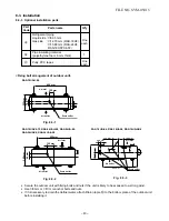
Air inlet
Drain outlet
<Fixing bolt arrangement of outdoor unit>
RAS-18UAH-E4
Fig. 8-3-1
RAS-18UAX4-T2, RAS-24UAH-E4, RAS-24UA-E4,
RAS-24UAX4, RAS-24UA-AR4
Fig. 8-3-2
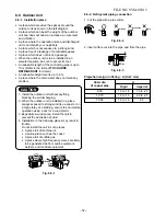
•
Secure the outdoor unit with fixing bolts and nuts if the unit is likely to be exposed to a strong wind.
•
Use
∅
8 mm or
∅
10 mm anchor bolts and nuts.
•
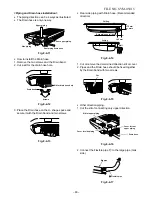
If it is necessary to drain the defrost water, attach Drain nipple
!
to the bottom plate of the outdoor unit
before installing it.
Part
Code
A
B
C
Q'ty
One
each
1
One
each
Parts name
Refrigerant piping
Liquid side :
∅
6.35 mm
Gas side
:
∅
12.70 mm (RAS-18UF)
:
∅
15.88 mm (RAS-24UF,
RAS-18UFPX4-T2)
Pipe insulating material
(polyethylene foam, 6 mm thick)
Putty, PVC tapes
Air outlet
Air outlet
Drain outlet
Air inlet
600 mm
325 mm
52 mm
120 mm
600 mm
340 mm
64 mm
120 mm
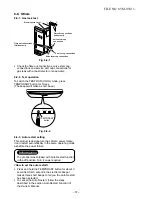
RA S-18UA-E4, RAS-18UAX4, RAS-18UA-AR4
F ig. 8-3-3
Air inlet
Air outlet
Drain outlet
600 mm
90 mm
125 mm
115 mm
32.5 mm
73 mm
102 mm
310 mm
7 mm
30
Æ


