background image

EN

11

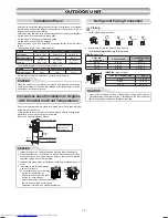
Flare at indoor 

unit side

Flare at outdoor 

unit side

Flare nut

Half union

Externally

threaded side

Internally

threaded side

Use a wrench to secure.

Use a torque wrench to tighten.

CAUTION

Align the centers of the connecting pipes and tighten the flare nut as far as 

possible with your fingers. Then tighten the nut with a spanner and torque 

wrench as shown in the figure.


Tightening connection

Do not apply excess torque. Otherwise, the nut may crack depending on 

the conditions.

(Unit : N·m)

Outer dia. of copper pipe 

Tightening torque

Ø6.35 mm

14 to 18 (1.4 to 1.8 kgf·m)

Ø9.52 mm

33 to 42 (3.3 to 4.2 kgf·m)

Ø12.70 mm

50 to 62 (5.0 to 6.2 kgf·m)

Evacuating

After the piping has been connected to the indoor unit, you can perform the 

air purge together at once.

AIR PURGE

Evacuate the air in the connecting pipes and in the indoor unit using a 

vacuum pump. Do not use the refrigerant in the outdoor unit. For details, 

see the manual of the vacuum pump.

•  Tightening torque of flare pipe connections

  The operating pressure of R32 is 

higher than that of R22 (approx. 

1.6 times). It is therefore necessary 

to firmly tighten the flare pipe 

connecting sections (which connect 

the indoor and outdoor units) up to the 

specified tightening torque. Incorrect 

connections may cause not only a 

gas leakage, but also damage to the 

refrigeration cycle.

Be sure to use a vacuum pump with counter-flow prevention function so that 

inside oil of the pump does not flow backward into pipes of the air conditioner 

when the pump stops.

(If oil inside of the vacuum pump enters the air conditioner, which use R32, 

refrigeration cycle trouble may result.)

1.  Connect the charge hose from the manifold valve to the service port of the 

packed valve at gas side.

2.  Connect the charge hose to the port of the vacuum pump.

3.  Open fully the low pressure side handle of the gauge manifold valve.

4.  Operate  the  vacuum  pump  to  start  evacuating.  Perform  evacuating  for 

about 15 minutes if the piping length is 25 meters. (15 minutes for 25 meters) 

(assuming  a  pump  capacity  of  27  liters  per  minute) Then  confirm  that  the 

compound pressure gauge reading is –101 kPa (–76 cmHg).

5.  Close the low pressure side valve handle of the gauge manifold valve.

6.  Open fully the valve stem of the packed valves (both gas and liquid sides).

7.  Remove the charging hose from the service port.

8.  Securely tighten the caps on the packed valves.

     Using a vacuum pump

Packed valve at liquid side

Service port (Valve core (Setting pin))

Packed valve at gas side

Vacuum

pump

Vacuum pump adapter for

counter-flow prevention

Charge hose

Handle Hi

(Keep full closed)

Manifold valve

Pressure gauge

Compound pressure gauge

Handle Lo

Charge hose

Connecting pipe

–101 kPa

(–76 cmHg)

CAUTION

•  KEEP IMPORTANT 6 POINTS FOR PIPING WORK.

  (1)  Take away dust and moisture (inside of the connecting pipes).

  (2)  Tighten the connections (between pipes and unit).

  (3)  Evacuate the air in the connecting pipes using a VACUUM PUMP.

  (4)  Check gas leak (connected points).

  (5)  Be sure to fully open the packed valves before operation.

  (6)  Reusable mechanical connectors and flared joints are not allowed 

indoors. When mechanical connectors are reused indoors, sealing 

parts shall be renewed. When flared joints are reused indoors, the 

flare part shall be refabricated.

     Packed valve handling precautions

•  Open the valve stem all the way out, but do not try to open it beyond the 

stopper.

•  Securely tighten the valve cap with torque in the following table.

Pipe size of Packed Valve

Size of Hexagon wrench

12.70 mm and smallers

A = 4 mm

15.88 mm

A = 5 mm


A

H

Hexagon wrench

is required.

Cap

Cap Size 

(H)

Torque

Valve Rod 

Cap

H17 - H19

14~18 N·m

(1.4 to 1.8 kgf·m)

H22 - H30

33~42 N·m

(3.3 to 4.2 kgf·m)

Service 

Port Cap

H14

8~12 N·m

(0.8 to 1.2 kgf·m)

H17

14~18 N·m

(1.4 to 1.8 kgf·m)

Service Port Cap

Valve Rod Cap

01_1121451198-EN.indd   11

4/26/2561 BE   10:06 AM

Содержание RAS-16PKVPG-E

Страница 1: ...AIR CONDITIONER SPLIT TYPE INSTALLATION MANUAL Indoor unit RAS 10PKVPG E RAS 13PKVPG E RAS 16PKVPG E Outdoor unit RAS 10PAVPG E RAS 13PAVPG E RAS 16PAVPG E 1121451198 ENGLISH R32 ...

Страница 2: ...oor unit is fixed to Installation plate with screws 9 n Drainage 9 OUTDOOR UNIT 10 n Installation Place 10 n Precautions about Installation in Regions with Showfall and Cold Temperatures 10 n Refrigerant Piping Connection 10 n Evacuating 11 ELECTRICAL WORKS 12 n Wiring Connection 12 n Power Supply and Connecting Cable Connection 13 n Power supply input Wiring Diagram 14 OTHERS 15 n Gas Leak Test 1...

Страница 3: ... incorrect use of this unit may cause severe injury or death CAUTION It indicates that incorrect use of this unit may cause personal injury 1 or property damage 2 1 Personal injury means a slight accident burn or electrical shock which does not require admission or repeated hospital treatment 2 Property damage means greater damage which affects assets or resources CAUTION This appliance must be co...

Страница 4: ...ELECTRIC PARTS MAY BE DAMAGED CHECK THE EARTH WIRE THAT IT IS NOT BROKEN OR DISCONNECTED BEFORE INSTALLATION DO NOT INSTALL NEAR CONCENTRATIONS OF COMBUSTIBLE GAS OR GAS VAPORS FAILURE TO FOLLOW THIS INSTRUCTION CAN RESULT IN FIRE OR EXPLOSION TO PREVENT OVERHEATING THE INDOOR UNIT AND CAUSING A FIRE HAZARD PLACE THE UNIT WELL AWAY MORE THAN 2 M FROM HEAT SOURCES SUCH AS RADIATORS HEATERS FURNACE ...

Страница 5: ...d possibly result in explosion and injury Thickness of copper pipes used R32 must be more than 0 8mm Never use copper pipes thinner than 0 8mm Do not perform flare connection inside a building or dwelling or room when joining the heat exchanger of indoor unit with interconnection piping Refrigerant connection inside a building or dwelling or room must be made by brazing or welding Joint connection...

Страница 6: ...ual carefully before installing the unit It contains further important instructions for proper installation The manufacturer shall not assume any liability for the damage caused by not observing the description of this manual REQUIREMENT OF REPORT TO THE LOCAL POWER SUPPLIER Please make absolutely sure that the installation of this appliance is reported to the local power supplier before installat...

Страница 7: ...Vacuum or wash and then dry them 4 Reinstall the air filters and close the air inlet grille ACCESSORY AND INSTALLATION PARTS No Parts name No Parts name 1 Installation plate x 1 2 Wireless remote control x 1 3 Battery x 2 4 Remote control holder x 1 5 Mounting screw ø4 x 25 l x 6 6 Flat head wood screw ø3 1 x 16 l x 2 7 Drain nipple x 1 for heating model only 8 Cap water proof x 2 for some models ...

Страница 8: ...it and wall and tilt the indoor unit for better operation The auxiliary piping can be connected to the left rear left rear right right bottom right or bottom left Do not allow the drain hose to get slack Make sure to run the drain hose sloped downward The flare connection should be installed outdoors Insulate the refrigerant pipes separately with insulation not together 6 mm thick heat resisting p...

Страница 9: ...ncrete wall with anchor bolts use the anchor bolt holes as illustrated in the below figure 3 Install the installation plate horizontally in the wall When installing the installation plate with a mounting screw do not use the anchor bolt holes Otherwise the unit may fall down and result in personal injury and property damage 1 After determining the pipe hole position on the mounting plate drill the...

Страница 10: ...polyethylene core or the like for bending pipe Use the handle of screwdriver etc Slit Cap Slit NOTE If the pipe is bent incorrectly the indoor unit may unstably be set on the wall After passing the connecting pipe through the pipe hole connect the connecting pipes to the auxiliary pipes and wrap the facing tape around them Do not perform flare connection inside a building or dwelling or room when ...

Страница 11: ... extension drain hose insulate the connecting part of extension drain hose with shield pipe NOTE The hole should be made at a slight downward slant on the outdoor side Arrange the drain pipe for proper drainage from the unit Improper drainage can result in dew dropping CAUTION This air conditioner has the structure designed to drain water collected from dew which forms on the back of the indoor un...

Страница 12: ...ain water does not raise any problems CAUTION Do not scratch the inner surface of the flared part when removing burrs Flare processing under the condition of scratches on the inner surface of flare processing part will cause refrigerant gas leak CAUTION When the outdoor unit is installed in a place where the drain water might cause any problems Seal the water leakage point tightly using a silicone...

Страница 13: ...p 3 Open fully the low pressure side handle of the gauge manifold valve 4 Operate the vacuum pump to start evacuating Perform evacuating for about 15 minutes if the piping length is 25 meters 15 minutes for 25 meters assuming a pump capacity of 27 liters per minute Then confirm that the compound pressure gauge reading is 101 kPa 76 cmHg 5 Close the low pressure side valve handle of the gauge manif...

Страница 14: ...e 1 2 N m 0 12 kgf m 7 Secure the cable with the cord clamp 8 Fix the terminal cover and attach front panel to the indoor unit 1 Remove the valve cover from the outdoor unit 2 Connect the cable to the terminals as identified with their respective matched numbers on the terminal block of indoor and outdoor unit 3 When connecting the cable to the outdoor unit terminals make a loop as shown in the in...

Страница 15: ...e Stripping length of the connecting cable Stripping length of the connecting cable Indoor Unit Indoor Unit Outdoor Unit Outdoor Unit 100 mm 10 mm 10 mm 90 mm Power supply terminal block L N Connecting terminal block 1 2 3 Earth line Connecting cable cord Power supply cord Earth line Connecting cable about 20 cm Plastic wire guide 45 mm 50 mm 10 mm 10 mm Connecting cable connect to terminal block ...

Страница 16: ... may cause some electrical part burn out 8 Incorrect or incomplete wiring is carried out it will cause an ignition or smoke 9 This product can be connected to main power supply Connection to fixed wiring A switch which disconnects all poles and has a contact separation at least 3mm must be incorporated in the fixed wiring Power supply input Wiring Diagram Indoor Terminal Block Power supply input O...

Страница 17: ...ame room or adjacent two rooms if operating a unit two units may receive the remote control signal simultaneously and operate In this case the operation can be preserved by setting either one remote control to B setting Both are set to A setting in factory shipment The remote control signal is not received when the settings of indoor unit and remote control are different There is no relation betwe...

Отзывы: