background image

FILE NO. SVM-04017-4

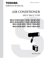
SERVICE MANUAL

AIR CONDITIONER

SPLIT WALL TYPE

RAS-13UKH-ES3 / RAS-13UAH-ES3
RAS-10UKH-ES3 / RAS-10UAH-ES3

RAS-13UK-ES3 / RAS-13UA-ES3
RAS-10UK-ES3 / RAS-10UA-ES3

Revised on Nov, 2005

Содержание RAS-10UA-ES3

Страница 1: ...FILE NO SVM 04017 4 SERVICE MANUAL AIR CONDITIONER SPLIT WALL TYPE RAS 13UKH ES3 RAS 13UAH ES3 RAS 10UKH ES3 RAS 10UAH ES3 RAS 13UK ES3 RAS 13UA ES3 RAS 10UK ES3 RAS 10UA ES3 Revised on Nov 2005 ...

Страница 2: ...3UA ES3 4 6 Outdoor Unit RAS 10UA ES3 5 REFRIGERATION CYCLE DIAGRAM 5 1 RAS 13UKH ES3 RAS 13UAH ES3 5 2 RAS 10UKH ES3 RAS 10UAH ES3 5 3 RAS 13UK ES3 RAS 13UA ES3 5 4 RAS 10UK ES3 RAS 10UA ES3 6 CONTROL BLOCK DIAGRAM 6 1 RAS 13UKH ES3 RAS 13UAH ES3 RAS 10UKH ES3 RAS 10UAH ES3 6 2 RAS 13UK ES3 RAS 13UA ES3 RAS 10UK ES3 RAS 10UA ES3 7 OPERATION DESCRIPTION 7 1 Outline of Air Conditioner Control 7 2 D...

Страница 3: ...g Procedure 9 2 Basic Check Items 9 3 Primary Judgement 9 4 Self Diagnosis by Remote Control Check Code 9 5 Troubleshooting Flowcharts 9 6 Troubleshooting for Remote Control 10 PART REPLACEMENT 10 1 Indoor Unit 10 2 Outdoor Unit 11 EXPLODED VIEWS AND PARTS LIST 11 1 Indoor Unit E Parts Assy 11 2 Indoor Unit 11 3 Outdoor Unit RAS 13UAH ES3 11 4 Outdoor Unit RAS 10UAH ES3 11 5 Outdoor Unit RAS 13UA ...

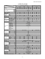
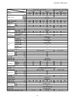
Страница 4: ...ection Connection type Flare connection pipe Maximum length m 15 1 One way Maximum height difference INDOOR UNIT RAS 13UKH ES3 RAS 13UK ES3 Height mm 275 Dimensions Width mm 790 Depth mm 208 Net weight kg 10 Evaporator type Finned tube Indoor fan type Cross flow fan High fan m3 h 630 650 630 Air volume Medium fan m3 h 520 550 520 Low fan m3 h 430 490 430 Fan motor output W 20 Air filter Honeycomb ...

Страница 5: ... Interconnection Connection type Flare connection pipe Maximum length m 10 1 One way Maximum height difference INDOOR UNIT RAS 10UKH ES3 RAS 10UK ES3 Height mm 275 Dimensions Width mm 790 Depth mm 208 Net weight kg 10 Evaporator type Finned tube Indoor fan type Cross flow fan High fan m3 h 570 610 610 Air volume Medium fan m3 h 460 520 460 Low fan m3 h 340 400 340 Fan motor output W 20 Air filter ...

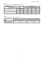
Страница 6: ...13UAH ES3 RAS 10UKH ES3 RAS 10UAH ES3 RAS 13UK ES3 RAS 13UA ES3 RAS 10UK ES3 RAS 10UA ES3 1 No need to charge 15 m or less 10 m or less extra refrigerant Temperature Condition JIS C9612 1994 Cooling Heating Indoor unit inlet air temperature DB 27 C 20 C WB 19 C 15 C Outdoor unit inlet air temperature DB 35 C 7 C WB 24 C 6 C FILE NO SVM 04017 ...

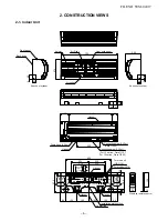
Страница 7: ... 45 40 190 275 45 235 120 53 Hanger Hanger Hanger Hanger Hanger Drain hose 0 54 m Connecting pipe 0 43 m Flare 6 35 Connecting pipe 0 33 m For stud bolt 8 10 For stud bolt 6 Installation plate outline Center line Minimum distance to ceiling 170 or more Minimum distance to ceiling 170 or more 65 or more Minimum distance to ceiling For 13 series Flare 12 7 For 10 series Flare 9 52 FILE NO SVM 04017 ...

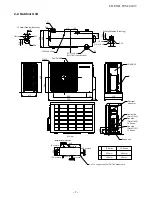
Страница 8: ... 436 4 x 11 Long holes For 8 10 anchor bolt 11 x 14 Hole 6 Hole 36 52 310 330 R15 270 600 90 780 62 COVER PV Electrical part cover Liquid side Flare 6 35 Gas side Flare 9 52 10 Series Gas side Flare 12 7 13 Series Service port 600 or more 13 Series A 600 mm 400 mm B 100 mm 45 mm 10 Series B or more A or more 100 or more 325 600 Air inlet Air outlet Installation dimension 120 75 5 4 B Z ZView FILE ...

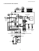
Страница 9: ...ER SUPPLY CIRCUIT C02 DC12V DC5V R21 VARISTOR MAIN P C BOARD MCC 862 T6 3A 250V P04 SG01 CN04 R22 YEL YEL YEL WHI GRN YEL CN11 AC FAN MOTOR INDOOR OUTDOOR BLK BLK 1 3 5 1 3 5 2 4 2 4 6 6 3 3 2 1 1 4 4 2 1 3 5 4 2 1 3 5 4 73 C THERMAL FUSE YEL PNK PNK 1 2 1 2 1 3 5 1 3 5 1 2 1 2 3 3 1 1 2 2 BLK BLK 1 1 2 2 1 3 R47 L 2 N BLU RED RED CAPACITOR WHI FAN MOTOR PNK Power Cord 4 BLU 5 BLU 6 BLU 7 BLU 8 BL...

Страница 10: ...CN04 R22 YEL YEL YEL WHI CN11 AC FAN MOTOR INDOOR OUTDOOR BLK BLK 1 3 5 1 3 5 2 4 2 4 6 6 3 2 1 4 2 1 3 5 4 2 1 3 5 4 PNK PNK 1 2 1 2 1 3 5 1 3 5 1 2 1 2 3 3 1 1 2 2 BLK BLK 1 1 2 2 1 3 R47 Louver motor CHASSIS BLK RED RED RED CAPACITOR WHI BLK SOLENOID COIL BLK CAPACITOR FAN MOTOR PNK WHI COMPRESSOR OUTDOOR TERMINAL BLOCK 3 1 4 L 2 N BLK 73 C THERMAL FUSE Power Cord POWER SUPPLY SINGLE PHASE 220 ...

Страница 11: ...01 BLK P04 TRANS TT 10 RED WHI BLU GRY CN05 CN06 1 2 1 2 1 2 1 2 WHI YEL YEL YEL YEL 2 1 4 3 PNK TEMP FUSE 220 240V 50Hz GRN YEL BLU N BRW L Heat Exchanger Sensor TC Thermo Sensor TA 73 C Single Phase PNK CN31 BLU CN14 CN25 BLU Infrared rays receiver and indication parts Power Cord BLU BLU BLU BLU BLU BLU BLU BLU WHI 1 2 6 5 8 7 9 11 10 1 4 3 2 6 5 8 7 9 11 10 1 4 3 2 6 5 8 7 9 11 10 1 4 3 2 6 5 8...

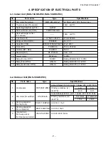
Страница 12: ...RF 2TK5R6 5 6Ω 2 W 12 Louver motor MP24GA 12VDC 13 Relay Comp RY01 DI12D1 Rating 20A AC250 V 12VDC 14 Relay Fan RY03 G5N 1A Rating 3A AC250 V 12VDC 15 Relay Solenoide RY04 G5N 1A Rating 3A AC250 V 12VDC 4 2 Outdoor Unit RAS 13UAH ES3 No Parts name Type Specifications Output Rated 1100 W 2 poles 1 phase 220 240V 50Hz 1 Compressor C S at 20 C 2 49 3 95 Output Rated 42 W 6 poles 1 phase 220 240V 50Hz...

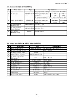
Страница 13: ...l SQ 373 AC 220 240V for 4 way valve 4 4 Indoor Unit RAS 13UK ES3 RAS 10UK ES3 No Parts name Type Specifications 1 Fan motor for indoor MMF 240 20 4A 1 AC Motor with 135 C thermo fuse 2 Thermo sensor TA sensor 10kΩ at 25 C 3 Switching transformer T01 SWT 47 4 Microcontroller unit IC30 TMP87CM40AN 2C67 5 Heat exchanger sensor 10kΩ at 25 C TC sensor 6 Line filter L01 LC SS11V 06270 27mH 600mA 7 Brid...

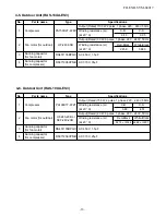
Страница 14: ...55BPQC AC 450 V 1 5µF for fan motor 4 Running capacitor DS371256CPNB AC 370 V 25µF for compressor 4 5 Outdoor Unit RAS 13UA ES3 No Parts name Type Specifications Output Rated 1100 W 2 poles 1 phase 220 240V 50Hz 1 Compressor PA150X2T 4FM1 Winding resistance Ω C R C S at 20 C 2 49 3 95 Output Rated 30 W 6 poles 1 phase 220 240V 50Hz 2 Fan motor for outdoor HF 240 30B Winding resistance Ω Red Black ...

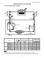
Страница 15: ... T1 P Refrigerant R410a 0 95 kg 12 7 6 35 Ambient temp conditions DB WB C Indoor Outdoor Standard 2 70 44 0 High 20 15 7 6 Heating Overload 1 3 20 3 70 52 0 59 0 Low 27 24 18 Low temperature 2 20 35 0 High 20 10 10 Standard 0 90 10 0 High 27 19 35 24 Cooling Overload 0 99 14 0 High 32 23 43 26 Low temperature 0 70 2 0 Low 21 15 21 15 Standard pressure P MPaG Surface temp of heat exchanger intercha...

Страница 16: ... 0 70 kg Capillary tube 1 0 x 1300l Accumulator Evaporator Ambient temp conditions DB WB C Indoor Outdoor Standard 2 45 40 0 High 20 15 7 6 Heating Overload 3 45 52 0 Low 27 24 18 Low temperature 2 10 35 0 High 20 10 10 Standard 0 90 11 0 High 27 19 35 24 Cooling Overload 1 07 16 0 High 32 23 43 26 Low temperature 0 85 5 0 Low 21 15 21 15 Standard pressure P MPaG Surface temp of heat exchanger int...

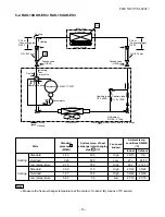
Страница 17: ...w 21 15 21 15 Standard pressure P MPaG Surface temp of heat exchanger interchanging pipe T1 C Fan speed indoor 50Hz Heat exchanger Indoor unit Cross flow fan Cooling Cooling Compressor Condenser Propeller fan Outdoor unit Capillary tube 1 5 x 500l PA150X2T 4FM1 Cooling Mark means check points of Gas Leak O D 12 7 mm O D 6 35 mm Cooling Packed valve 12 7 Packed valve 6 35 0 39 m Connecting pipe 12 ...

Страница 18: ...52 0 49 m Connecting pipe 6 35 T1 P Refrigerant R410a 0 65 kg Evaporator Capillary tube 1 5 x 1100l Ambient temp conditions DB WB C Indoor Outdoor Standard 0 95 11 0 High 27 19 35 24 Cooling Overload 1 15 15 0 High 32 23 43 26 Low temperature 0 85 5 0 Low 21 15 21 15 Standard pressure P MPaG Surface temp of heat exchanger interchanging pipe T1 C Fan speed indoor 50Hz Note Measure the heat exchange...

Страница 19: ...Fan Motor Louver Control 3 minutes Delay at Restart for Compressor Processing Temperature Processing Motor Revolution Control Timer Initiallizing Circuit Clock Frequency Oscillator Circuit Thermo Sensor Current Sensor Compressor Current Infrared Rays Signal Reciver REMOTE CONTROL 18 6 CONTROL BLOCK DIAGRAM 6 1 RAS 13UKH ES3 RAS 13 UAH ES3 RAS 10UKH ES3 RAS 10 UAH ES3 Remote Control Operation Mode ...

Страница 20: ...y Filter Sign Display Auto Fan Sign Display Indoor Fan Motor Louver Motor Louver ON OFF Signal Compressor ON OFF Signal Power Supply Circuit Noise Filter Relay Driver Louver Driver Relay RY01 220 240 V 50Hz Compressor Outdoor Fan Motor Initiallizing Circuit Clock Frequency Oscillator Circuit Louver Control 3 minutes Delay at Restart for Compressor Processing Temperature Processing Motor Revolution...

Страница 21: ...d by the indoor unit controller The controller operates the indoor fan motor based upon commands transmitted by the remote control and transfers the operation commands to the outdoor unit controller The outdoor unit controller receives operation commands from the indoor unit and operates the outdoor fan motor and the compressor 1 Role of indoor unit controller The indoor unit controller receives t...

Страница 22: ...rked with 1 are calculated and controlled by the difference in motor speed between M and L Fig 7 2 1 Setting of air flow FAN AUTO 2 The Hi POWER operation cannot be set 7 2 2 Cooling operation MODE button on the remote control is set to the cooling operation 1 The compressor 4 way valve outdoor fan and operation display on the remote control are controlled as shown in Fig 7 2 2 Fig 7 2 2 2 When FA...

Страница 23: ...d as shown in Fig 7 2 4 Fig 7 2 4 2 The microcontroller turns the compressor on and off at the regular intervals 4 to 6 minutes While the compressor is turning off the indoor fan motor operates in the SUPER LOW position The pattern of operation depending on the relation between room temperature and preset temperatures is shown in Fig 7 2 5 Fig 7 2 5 3 FAN button on the remote control is set to AUT...

Страница 24: ...en the preset temperature and the room temperature at which the automatic operation has started as shown in Fig 7 2 9 The Fan only operation continues until the room temperature reaches a level at which another mode is selected 2 Temporary Auto When the TEMPORARY button on the indoor unit is pushed the preset temperature is fixed at 24 C and the indoor unit is controlled as shown in Fig 7 2 9 Fig ...

Страница 25: ...conditioner operates at normal airflow level 3 Heating operation Heat pump model only The preset temperature increases 2 C The value of the preset temperature on the remote control does not change The indoor unit operates in normal heating mode except the preset temperature is higher 2 C 4 The Hi POWER mode can not be set in Dry or Fan only operation 7 4 High Temperature Limit Control Heat pump mo...

Страница 26: ...4th cycle is 10 minutes When the outdoor temperature is very low however the defrost operating time is 10 minutes Fig 7 6 2 DEFROST LAMP During defrost operation the PRE DEF lamp is on and the indoor and outdoor fans are off The compressor start protection timer is inter looked with the PRE DEF lamp So the PRE DEF Lamp is off the fans stop for about 3 minutes after the START STOP button is turned ...

Страница 27: ...S3 Fig 7 7 1 2 Current limit control Heating operation Control is performed as shown in Fig 7 7 2 RAS 13UKH ES3 RAS 10UKH ES3 Fig 7 7 2 Remark This function is available only for heat pump model Cooling models have no a current sensor C T Input current 13 5A 19 2A I4 12 5A 17 8A I3 10A 15 6A I2 9A 15 0A I1 Compressor Outdoor fan More than I4 continues for 3 seconds OFF More than I3 continues for 5...

Страница 28: ... proceed as follows The power supply to the unit must be on the function will not set if the power is off Push the TEMPORARY button located in the center of the front panel continuously for three seconds The unit receives the signal and beeps three times The unit then restarts operating automatically in the event of power supply being accidentally shut down While the filter check lamp is on the TE...

Страница 29: ...r check lamp Press FILTER button on the remote control OR push TEMPORARY button on the indoor unit Note If TEMPORARY button is pushed while the filter check lamp is not indicating the indoor unit will start the Automatic Operation Operation Motions Push TEMPORARY button for more The unit is on standby than three seconds The unit starts to operate The orange lamp is on After approx three seconds Th...

Страница 30: ...ry and property damage can result if the unit falls Before doing the electrical work attach an approved plug to the power supply cord Also make sure the equipment is properly earthed Appliance shall be installed in accordance with national wiring regulations If you detect any damage do not install the unit Contact your TOSHIBA dealer immediately CAUTION Exposure of unit to water or other moisture ...

Страница 31: ... process following installation conditions do apply 1 The power connection for the air conditioner has to be done at the main power distribution This distribution has to be of an impedance Normally the required impedance is reached at a 32A fusing point Air conditioner fuse has to be 16A max 2 No other equipment should be connected to this power line 3 For detailed installation acceptance please c...

Страница 32: ...ant pipes separately with insulation not together For the rear left and left piping Insert the cushion between the indoor unit and wall and tilt the indoor unit for better operation 1 Installation plate Wall Left Rear left Bottom left 6 mm thick heat resisting polyethylene foam Saddle Do not allow the drain hose to get slack Make sure to run the drain hose sloped downward Cut the piping hole slope...

Страница 33: ...ement of outdoor unit Fig 8 3 1 Secure the outdoor unit with fixing bolts and nuts if the unit is likely to be exposed to a strong wind Use 8 mm or 10 mm anchor bolts and nuts If it is necessary to drain the defrost water attach drain nipple 9 and cap water proof to the bottom plate of the outdoor unit before installing it Air inlet Air outlet Drain outlet 600 mm 90 mm 125 mm 115 mm 32 5 mm 73 mm ...

Страница 34: ... Part No 7 8 9 Others Name Owner s manual Installation manual The part marked with asterisk is packaged with the outdoor unit This model is not equipped with an extension drain hose Option For the extension drain hose use an optionally available RB 821SW or commercially available one Part name Q ty Mounting screw 4 x 25 s x 6 Pan head wood screw 3 1 x 16 s x 2 Drain nipple x 1 For Heat pump model ...

Страница 35: ...ereo equipment This is necessary to prevent image disturbances or noise interference The location of the remote control should be determined as shown below Fig 8 4 1 5 m 5 m 45 45 75 7 m 7 m Top view Indoor unit Axial distance Reception range Reception range Remote control Indoor unit Remote control Side view 8 4 2 Cutting a hole and mounting installation plate Cutting a hole When installing the r...

Страница 36: ...for appropriate mounting screws 7 NOTE Secure four corners and lower parts of the installation plate with 4 to 6 mounting screws to install it Installation plate Keep horizontal direction RAS 13UKH ES3 RAS 10UKH ES3 RAS 13UK ES3 RAS 10UK ES3 Power source 50Hz 220 240 V Single phase Maximum 12A 7 5A running current Plug socket 16A fuse rating Power cord 1 3 mm2 or more 1 mm2 or more 8 4 3 Electrica...

Страница 37: ... 3 Slightly open the lower part of the front panel then pull the upper part of the front panel toward you to remove it from the rear plate 4 After removing the front panel remove the power cord connect cover and the cord camp 5 Connect and secure the power supply cord and secure the cord camp and the power connect cover 6 Put the power supply cord through the notch 7 Be sure to smooth the notch wi...

Страница 38: ...air inlet grille on the indoor unit CAUTION Be sure to refer to the wiring system diagram labeled inside the front panel Check local electrical cords and also any specific wiring instructions or limitations For RAS 13 10UKH Fig 8 4 9 Stripping length of the connecting cable Fig 8 4 10 Earth line Connecting cable Terminal cover Screw Cord clamp Terminal block about 15 cm Screw Screw Earth line Conn...

Страница 39: ... 8 4 15 How to fix the drains cap 1 Insert hexagonal wrench 4 mm in a center head Fig 8 4 16 2 Firmly insert drains cap Fig 8 4 17 CAUTION Firmly insert the drain hose and drain cap otherwise water may leak In case of right or left piping After scribing slits of the front panel with a knife or a making off pin cut them with a pair of nippers or an equivalent tool Fig 8 4 18 In case of bottom right...

Страница 40: ...ing tape wound on the connecting pipe to avoid double taping at the joint moreover seal the joint with the vinyl tape etc Since dewing results in a machine trouble make sure to insulate both the connecting pipes Use polyethylene foam as insulating material When bending a pipe carefully do it not to crush it Installation plate Auxiliary pipes Indoor unit Connecting cable 8 4 6 Indoor unit fixing 1 ...

Страница 41: ...s A place which is not exposed to a strong wind A place free of a leakage of combustible gases A place which does not block a passage When the outdoor unit is to be installed in an elevated position be sure to secure its feet An allowable length of the connecting pipe is up to 10 m RAS 10UA or 15 m RAS 13UA An allowable height level is up to 5 m RAS 10UA or 6 m RAS 13UA A place where the drain wat...

Страница 42: ...Check gas leak connected points Flare nut Half union Externally threaded side Internally threaded side Flare at indoor unit side Flare at outdoor unit side Mark line Outer dia Tightening torque of copper pipe 6 35 16 to 18 1 6 to 1 8 kgf m 9 52 30 to 42 3 0 to 4 2 kgf m 12 70 50 to 62 5 0 to 6 2 kgf m 8 5 2 Refrigerant piping connection 1 Cut the pipe with a pipe cutter Fig 8 5 2 2 Insert a flare ...

Страница 43: ...ir conditioner when the pump stops 1 Connect the charge hose from the manifold valve to the service port of the gas side packed valve 2 Connect the charge hose to the port of the vacuum pump 3 Open fully the low pressure side handle of the gauge manifold valve 4 Operate the vacuum pump to start evacuating Perform evacuating for about 15 minutes if the piping length is 20 meters 15 minutes for 20 m...

Страница 44: ...2 or more 8 6 How to Set Remote Control Selector Switch When two indoor units ae installed in seperated rooms there is no need to change the selector switch Remote control selector switch When two indoor units are installed in the same room or the adjacent two rooms they may be controlled simultaneously with a single remote control To prevent this set either unit and its remote control to B settin...

Страница 45: ...t follow the steps described in the section Auto Restart Function of the Owner s Manual Valve stem cap connection Service cap connection Valve cover 2 Set the remote control selector switch with the remote control B is indicated on the liquid crystal display when setting remote control selector switch to B A is not indicated on the display even if the selector switch is set to A 1 Load the remote ...

Страница 46: ...arts 6 The outdoor fan motor stops in the Heating operation 7 The compressor is not turned on even though the room temperature is in the range that the compressor is turned on 8 The operation mode changes in the Automatic operation 9 The Fan only operation continues in the Automatic operation 10 The Hi POWER operation does not work No Operation of air conditioner Descriptions The OPERATION lamp bl...

Страница 47: ...amp is blinking 5Hz F OPERATION and TIMER lamps are blinking 5Hz G OPERATION TIMER and PRE DEF or FAN ONLY for cooling only model lamps are blinking Table 9 3 2 Diagnosis by detective operation The remote control does not work The outdoor fan does not rotate Turn off the power supply once then turn it on Try to operate the remote control The compressor operates The compressor does not operate The ...

Страница 48: ... If there is no fault with a code the indoor unit will beep once Pi and the display of the remote control will change as follows Check the unit with all 35 check codes 00 to 22 as shown in Table 9 4 1 Press 9TEMP button to change the check code backwards If there is a fault the indoor unit will beep for 10 seconds Pi Pi Pi Note the check code on the display of the remote control 2 digits alphanume...

Страница 49: ...heck P C board 1 Check heat thermal fuse is blow or not Terminal block part 2 If the thermal fuse is not blow check indoor fan motor Refer to trouble shooting flow charts Replace P C board 1 Check connective cable correct if wiring is wrong 2 Check thermal fuse and Terminal blocks 3 If it is OK check P C board 1 If overload relay and thermostat for compressor are OK check refrigerant cycle 2 If re...

Страница 50: ... YES YES NO NO NO NO NO NO Does the thermal fuse blow Under PF Terminal Wrong wiring of AC cord or connecting cable is defective Replace the thermal fuse set Check connection Is the indication voltage DC12 V or 5 V of main P C board correct Does the CN13 connector the wrong connecting P C board is defective Replace the main P C board Is the voltage across C02 measured DC310 V 340 V Refer to the pa...

Страница 51: ...cable is defective Replace the thermal fuse set Check connection Is the indication voltage DC12V or 5V of main P C board correct Does the CN14 connector the wrong connecting P C board is defective Replace the main P C board Is the voltage across C50 measured DC12 15V Refer to the paragraph Pre check or defective circuit before power P C board block Is the secondary voltage of transformer TT 10 mea...

Страница 52: ...the wiring of the power relay is returned to the normal procedure To the paragraph of No Power turns on YES NO NO YES RAS 10UKH ES3 RAS 13UKH ES3 Double winding Indoor terminal block Power terminal block Black White Blue Brown RY01 P C board CN31 T02 Bind Band Indoor terminal block Power terminal block Black White Blue Brown RY01 P C board CN31 T02 1 2 3 4 N L 1 2 3 4 N L FILE NO SVM 04017 ...

Страница 53: ... turn it on after 5 seconds See Power can not be turned on NO NO NO NO YES YES YES YES Does the power turn on by pushing the START STOP button of the remote control Is AC 220 240 V supplied between terminal block 1 2 Relays RY01 or IC31 or IC30 is failure Replace the P C board Is cable connection between indoor and outdoor units correct Correct cabling between indoor and outdoor units Does the OPE...

Страница 54: ...ection between indoor and outdoor units correct Correct cabling between indoor and outdoor units Is the voltage across the outdoor terminal 1 2 AC 220 240 V Cables between indoor and outdoor units are defective Are all the cords for compressor normal Re wire or replace the defective cords Is the compressor motor winding normal Check the winding resistor Compressor is defective Is the capacitor for...

Страница 55: ...V Relays RY03 or IC31 or IC30 is failure Replace the P C board Is cable connection between indoor and outdoor units correct Correct cabling between indoor and outdoor units Is the voltage across the terminal 2 4 Heat pump model 1 2 Cooling only model AC 220 240 V Cables between indoor and outdoor units are defective Are all the cords for outdoor fan motor normal Correct the wire or replace the def...

Страница 56: ...s the voltage across the indoor terminal 2 3 220 240 V Relays RY04 or IC31 or IC30 is failure Replace the P C board Is cable connection between indoor and outdoor units correct Correct cabling between indoor and outdoor units Is the voltage across the outdoor terminal 2 3 220 240 V Cables between indoor and outddor units are defective Is the wiring of solenoid coil for 4 way valve normal Solenoid ...

Страница 57: ...nge the setting of cooling to hight fan Does the cross flow fan rotate normally Repair the bearing of the fan Thermal fuse operated due to prevent temperature rising cause of incompleted connecting Shut off the power supply Turn on the power supply Does the fan speed become higher Operation stops Motor control circuit failure IC30 IC03 T01 or 12 V power circuit failire D03 Q33 Replace the P C boar...

Страница 58: ...o hight fan Does the cross flow fan rotate normally Repair the bearing of the fan Thermal fuse operated due to prevent temperature rising cause of incompleted connecting Shut off the power supply Turn on the power supply Does the fan speed become higher Operation stops Motor control circuit failure IC30 IC03 TT10 or 12 V power circuit failire IC31 Replace the P C board Is the rotation signal DC 5 ...

Страница 59: ...y switch of the air conditioner main unit to TEST RUN or TEMPORARY AUTO Can any signal tone be heard in a trasistor radio when transmitting within 5 cm distance from the radio P C board is failure Replace P C board Is operation possible when the transmitter is moved nearer to the infrared sinnal receiver of the air conditioner Battery life Replace the batteries Reset the remote control by use the ...

Страница 60: ...d hold the Whole housing Do not pull at the lead wire 2 Inspection procedres 1 When a P C board is judged to be defective check for disconnection burning or discolora tion of the copper foil pattern or this P C board 2 The P C board consists of the following 2 parts a Main P C board part power relay indoor fan motor drive circuit and control circuit C P U and peripheral circuits buzzer drive circu...

Страница 61: ... GND Between pin 11 of IC31 and GND 2 Between No 1 and 2 of connect ing cable terminal block AC 220 240 V 1 All indicators light for 3 sec 2 Indicators do not indicate normally after approximate 3 sec 1 Compressor does not operate 2 OPERATION lamp blinks 1 Compressor does not operate 2 OPERATION lamp blinks 1 Motor does not rotate The key operation is accepted 2 The Motor rotates but it vibrates t...

Страница 62: ...D Between pin 11 of IC31 and GND 2 Between No 1 and 2 of connect ing cable terminal block AC 220 240 V 1 All indicators light for 3 sec 2 Indicators do not indicate normally after approximate 3 sec 1 Compressor does not operate 2 OPERATION lamp blinks 1 Compressor does not operate 2 OPERATION lamp blinks 1 Motor does not rotate The key operation is accepted 2 The Motor rotates but it vibrates too ...

Страница 63: ...n time of restart delay timer 1 Set the operation mode temperature and air flow code timer short code 3 Pushing START STOP buttons sends operation are released The status is kept even if CHK and CLR buttons and the timer short mode is waited pushed in this case the check mode is released 2 Push the CLR button while keeping CHK button rate to be applied with the timer short mode 4 The timer short m...

Страница 64: ... the LED unit Then remove the LED unit and the electrical part box from the main unit How to mount the electrical part 1 To put back the electrical part box lock it to the upper hook of the back body 2 Tighten the screw on the electrical part box 3 Connect the 3 connectors and arrange the wiring same as original condition and then tighten the screw from the LED unit to the back body 4 Attach the T...

Страница 65: ...the fan motor Notice To assemble cross flow fan and fan motor to the unit please turn the fan motor unit the center of its terminal meets the lowest point of band motor R point A Fix the cross flow fan with the set screw at the position where the gap between the back body and the right surface of the cross flow fan is 6 mm 1 Remove the front panel electrical part horizontal louver heat exchanger a...

Страница 66: ... out upward 1 Perform the common procedure 1 2 Remove the fixing screw and the capacitor band 1 Screw 4 x 10L 3 Disconnect the lead wires 1 Perform the common procedure 1 2 Remove the fixing screw and the capacitor band 1 Screw 4 x 10L 3 Disconnect the lead wires 10 2 Outdoor Unit 1 Common procedure 2 Capacitor for compressor 3 Capacitor for fan motor No Part name Procedures Remarks Cord clamp 3 S...

Страница 67: ...al Block 2P 403 43T69004 TC Sensor 10kΩ 25 C 404 43T69005 Sensor Thermostat 10kΩ 25 C 405 43T69079 P C Board ASSY WRS LED MCC 861 Location Part Description No No 406 43T69364 Fuse Temperature 73 C 410 43T62003 Cord Clamp 43T69390 P C Board RAS 10UKH ES3 P C Board RAS 13UKH ES3 43T69391 411 For Heat pump model 402 43T60002 Terminal Block 3P ...

Страница 68: ...r 10kΩ 25 C 404 43T69005 Sensor Thermostat 10kΩ 25 C 405 43T69079 P C Board ASSY WRS LED Location Part Description No No 406 43T69364 Fuse Temperature 73 C 410 43T62003 Cord Clamp 43T69369 P C Board RAS 13UK ES3 43T69370 MCC 861 411 411 P C Board RAS 10UK ES3 402 43T60002 Terminal Block 3P For Cooling model Transformer 43T69361 412 ...

Страница 69: ...iption No No 201 43T00391 Front Panel Assy 202 43T09327 Inlet Grille Assy 203 43T03302 Back Body Assy 204 43T80301 Air Filter 205 43T09328 Horizontal Louver 206 43T08395 LED Panel Assy For Heat pump model 206 43T08394 LED Panel Assy For Cooling only model 207 43T70002 Drain Hose 208 43T79301 Cap Drain 209 43T21321 Motor Louver MP24Z DC 12V 210 43T44322 Refrigeration Cycle Assy For 10 Series 210 43...

Страница 70: ... 6 35 Dia 12 43T46318 Valve packed 12 7 Dia 13 43T47331 Bonnet 6 35 Dia 14 43T47333 Bonnet 12 7 Dia Location Part Description No No 15 43T63303 Fixing plate valve 16 43T47011 Tube capillary 1 5ID 17 43T41321 Compressor PA150XT2 4FM1 18 43T47324 Bolt compressor M6 19 43T49008 Cushion rubber 20 43T52310 Packed valve cover assembly 21 43T55306 Capacitor Plastic film 35m F 370 V 22 43T55314 Capacitor ...

Страница 71: ...T46317 Valve packed 6 35 Dia 12 43T46320 Valve packed 9 52 Dia 13 43T47331 Bonnet 6 35 Dia Location Part Description No No 14 43T47332 Bonnet 9 52 Dia 15 43T63303 Fixing plate valve 16 43T47007 Tube capillary 1 2IDA 17 43T41327 Compressor PA108X1T 4FZ1 18 43T47325 Bolt compressor M6 19 43T49001 Cushion rubber 20 43T52310 Packed valve cover assembly 21 43T55305 Capacitor Plastic film 25m F 370 V 22...

Страница 72: ...43T46317 Valve packed 6 35 Dia 11 43T46307 Valve packed 12 7 Dia 12 43T47331 Bonnet 6 35 Dia 13 43T47333 Bonnet 12 7 Dia Location Part Description No No 14 43T63303 Fixing plate valve 15 43T47008 Tube capillary 1 5IDA 16 43T41321 Compressor PA150XT2 4FM1 17 43T47324 Bolt compressor M6 18 43T49008 Cushion rubber 19 43T52310 Packed valve cover assembly 20 43T00369 Upper cabinet assembly 21 43T55306 ...

Страница 73: ...a 11 43T46320 Valve packed 9 52 Dia 12 43T47331 Bonnet 6 35 Dia 13 43T47332 Bonnet 9 52 Dia Location Part Description No No 14 43T03303 Fixing plate valve 15 43T47008 Tube capillary 1 5IDA 16 43T41327 Compressor PA108X1T 4FZ1 17 43T47325 Bolt compressor M6 18 43T49001 Cushion rubber 19 43T52310 Packed valve cover assembly 20 43T00395 Upper cabinet assembly 21 43T55305 Capacitor Plastic film 25µF 3...

Страница 74: ... 71 FILE NO SVM 03006 TOSHIBA CARRIER THAILAND CO LTD 144 9 MOO 5 BANGKADI INDUSTRIAL PARK TIVANON ROAD TAMBOL BANGKADI AMPHUR MUANG PATHUMTHANI 12000 THAILAND ...

Отзывы: