


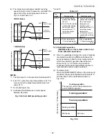
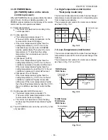
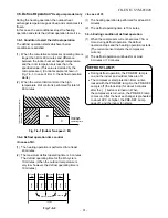


−
19
−
FILE NO. SVM-05020
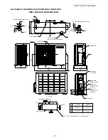
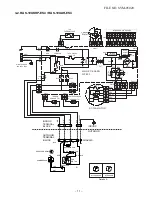
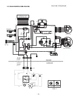
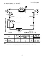
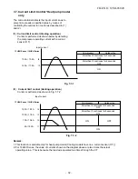
5. REFRIGERATION CYCLE DIAGRAM
5-1. RAS-13UKHP-ES
4
/ RAS-13U
AH-ES4
Note :
Measure the heat exchanger temperature at the center of U-bend. (By means of TC sensor)
*1
During heating overload operation, a value for the high temperature limit control operation is included.
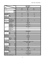
Ambient temp.
conditions DB/WB
(°C)
Indoor
Outdoor
Standard 2.7
3
43.5
High 20/15 7/6
Heating Overload*1 3.20 ~ 3.
60
52.0 ~ 58.5
Low 27/
−
24/18
Low temperature 2.20
35.0
High 20/
−
−
10/
−
10
Standard 0.
85
10.0
High 27/19 35/24
Cooling Overload
0
.
99
14.0
High 32/23 43/26
Low temperature 0.
65
2.0
Low
21/15 21/15
Standar d
pressure P
(MPaG)
Surface temp. of heat
exchang er inter changing
pipe T1 (°C)
Fan speed
(indoor)
50Hz
Heat exchanger
Indoor unit
Cross flow fan
Cooling
Heating
4-way valve
Heating Cooling Compressor
Accumulator
Heat exchanger
Propeller fan
Outdoor unit
Capillary tube
∅
1.
0
x
4
00
l
Capillary tube
∅
1.5x1
2
00
l
PA150X2
C-4FT
Cooling
Heating
Mark( )means check points of Gas Leak.
O.D.:12.7mm
O.D.:6.35mm
Cooling
Heating
Packed valve
Packed valve
0.39m
(Connecting pipe)
0.49m
(Connecting pipe)
T1
P
Refrigerant
R410A :
0
.
95
kg.
(
∅
12.7)
(
∅
6.35)
∅
12.7
∅
6.35
•
•


