– 21 –
41-EN
42-EN
9
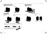
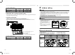
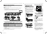
Close the connectors between the [U1, U2] and [U3, U4] terminals on all the header outdoor
units (As shown).
U1
U3 U4
U2
U5 U6
S
S
9
TO
INDOOR
UNIT
TO
CENTRAL
CONTROLLER
TO
OUTDOOR
UNIT
SHIELD
SHIELD
10
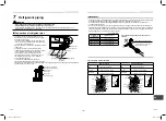
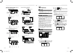
Set the central control address.
(For setting the central control address, refer to the installation manuals for the central control devices.)
SW15
SW04
1 2
SW13
SW14
SW01 SW02 SW03
D600 D601 D602 D603 D604
SW05
SW30
7-segment
display
Header unit interface P.C. board
2
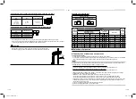
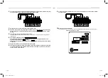
The connectors between the [U1U2] and [U3U4] terminals on all the header outdoor units (that
will be connected to the central control) should be open as shown.
U1
U3 U4
U2
U5 U6
S
S
2
TO
INDOOR
UNIT
TO
CENTRAL
CONTROLLER
TO
OUTDOOR
UNIT
SHIELD
SHIELD
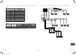
3
Energize indoor units
fi
rst, and then energize outdoor units.
4
About 1 minute after turning energizing the outdoor units, con
fi
rm that the 7-segment display
on the interface P.C. board of the header outdoor unit indicates
U. 1. L08
. The U.1. will be
fl
ashing.
5
Press SW15 to start the automatic address setting.
It normally takes 5 minutes, but may take as long as 10 minutes to complete the auto address setting for 1
refrigerant line.
6
The 7 segment display will indicate
Auto 1
→
Auto 2
→
Auto 3
.
When the address sequence has covered all the fan coils for a refrigerant line auto - the 7
segment display will indicate
U. 1.
fl
ashing.
When the
fl
ashing stops and the display indicates
U. 1.
without
fl
ashing, the address setting
is complete.
7
Repeat
steps
4
to
6
for every refrigerant line in the system.
8
After completing address setting of all systems, turn off DIP switch 2 of SW30 on the interface
P.C. boards of all the header outdoor units connected to the same central control, except the
unit that has the lowest address.
1122001201_EN FR.indd 21
1122001201_EN FR.indd 21
9/2/16 1:30 PM
9/2/16 1:30 PM

