background image

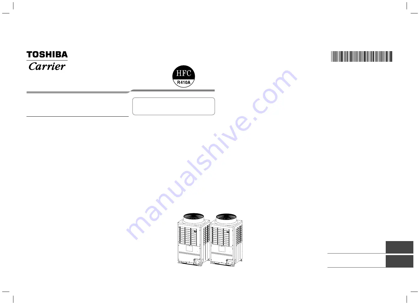
AIR CONDITIONER (MULTI TYPE)

Installation Manual

Outdoor Unit

Model name:

<Heat Recovery Model>

MMY-MAP0726FT2P-UL

1122001201

English

Français

Installation Manual 

1

Manuel d’installation 

32

For OUTDOOR USE only

Pour une UTILISATION EN EXTÉRIEUR 

uniquement

1122001201_EN FR.indd   1

1122001201_EN FR.indd   1

9/2/16   1:30 PM

9/2/16   1:30 PM

Содержание MMY-MAP0726FT2P-UL

Страница 1: ...el name Heat Recovery Model MMY MAP0726FT2P UL 1122001201 English Français Installation Manual 1 Manuel d installation 32 For OUTDOOR USE only Pour une UTILISATION EN EXTÉRIEUR uniquement 1122001201_EN FR indd 1 1122001201_EN FR indd 1 9 2 16 1 30 PM 9 2 16 1 30 PM ...

Страница 2: ...e and on tags stickers and labels attached to the equipment Follow all safety codes Wear safety glasses and work gloves Use care in handling rigging and setting bulky equipment Read these instructions thoroughly and follow all warnings or cautions included in literature and attached to the unit Consult local building codes and National Electrical Code NEC for special requirements Recognize safety ...

Страница 3: ...ler or qualified service person is allowed to carry out the electrical work of the air conditioner When connecting the electrical wires repairing the electrical parts or undertaking other electrical jobs wear gloves to provide protection for electricians and from heat insulating shoes and clothing to provide protection from electric shocks Failure to wear this protective gear may result in electri...

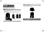
Страница 4: ...Flare the connector on the outdoor unit for installation Attached pipe Ø3 4 for draw out downward 1 3 Installation of R410 air conditioner This air conditioner adopts the HFC refrigerant R410A which does not deplete the ozone layer To prevent mixing of refrigerant or refrigerating oil the size of the charge port of the main unit or connecting section of the installation tool differs to that of an ...

Страница 5: ... communication equipment is set Malfunction or abnormal control of the air conditioner or interference to devices listed above may occur Places where discharged air from the outdoor unit blows against the windows of a neighbour s house Places unable to bear the weight of the unit Places with poor ventilation Installation space Unit in mm Leave space necessary for running installation and servicing...

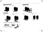
Страница 6: ...ie the unit from 4 sides Apply padding in positions where the rope comes in contact with the outdoor unit so that no damage is caused to the outer surface of the outdoor unit There are reinforcing plates on the side surfaces so the rope cannot be passed through Rectangular holes for handling Front Back Side Correct Correct Incorrect Incorrect Incorrect Fork of the forklift Plaster board Plaster bo...

Страница 7: ...priate for an anchor bolt Unit in mm L Recommendation 7 9 200mm at least 0 8 20mm or more L M12 anchor bolt 4 positions unit 0 8 20 Anchor bolt positions are as shown below A A B L B Continuous hole 0 6 0 8 15 20 long hole L 11 4 290 Model type A B L MAP0726 27 6 700 39 0 990 Recommendation 7 9 200 at least 0 8 20 or more 2 To draw out the refrigerant pipe from the underside set the height of the ...

Страница 8: ...or the liquid side there is no restriction for its angle A B Horizontal line Horizontal line A arrow view B arrow view Within 15 degrees Within 15 degrees Do not connect a branch unit vertically 19 7 500mm or more At a level position In case of using the Y shaped branching joint for connecting between outdoor units Discharge gas joint and Suction gas joint please keep the straight part of at least...

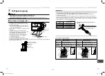
Страница 9: ...spanners to loosen or tighten the flare nut If a single spanner is used the required level of tightening cannot be obtained Tighten the flare nut with the specified torque If it is hard to loosen or tighten the flare nut of the balance pipe or packed valve of the liquid side with two spanners loosen or tighten the flare nut while holding the valve mounting plate with a spanner Ball valve of discha...

Страница 10: ...7 8 22 2 7 8 0 0012 22 22 0 03 0 88 0 0012 0 0012 23 36 0 03 0 03 0 43 11 0 39 10 0 0063 or less 0 16 or less 0 032 0 82 Ø1 1 8 28 58 1 1 8 0 0012 28 58 0 04 1 13 0 0024 0 0008 28 75 0 06 0 02 0 51 13 0 47 12 0 0079 or less 0 20 or less 0 039 1 00 Selection of pipe size Capacity code of indoor and outdoor units Selection of pipe material For the indoor unit the capacity code is decided at each cap...

Страница 11: ...unit Table 1 Indoor unit capacity type Indoor capacity code Equivalent to capacity 007 type 7 5 009 type 9 5 012 type 12 015 type 15 4 018 type 18 021 type 21 024 type 24 027 type 27 030 type 30 036 type 36 042 type 42 048 type 48 054 type 54 072 type 72 096 type 96 Table 2 Outdoor unit capacity type Outdoor unit capacity code Maximum number of indoor units 1 Height difference between indoor units...

Страница 12: ...r unit connection piping kit Total capacity code of the outdoor units at downstream side 1 Model name Below 144 RBM BT14FUL 10 Flow Selector unit Single port type 7 Total capacity code of outdoor units on downstream side from FS unit Model name Below 38 RBM Y0383FUL 38 to below 61 RBM Y0613FUL 61 to 96 or less RBM Y0963FUL Multi port type 8 Total capacity code of outdoor units on downstream side f...

Страница 13: ...length from the first branch Li The longest piping length in Flow selector unit group Ln Flow Selector Indoor unit Indoor unit Flow Selector unit Multi port type Indoor unit connecting pipe Y shaped branching joint H4 Height difference between indoor units H2 Height difference between outdoor and indoor units CAUTION Please use the appropriate pipe when the pipe size is Ø3 4 or more Table 3 Outer ...

Страница 14: ... first branch Li H1 9 8 ft 164 L3 L4 L5 L6 L7 L8 o L3 L9 L10 t H1 9 8 ft 213 Maximum equivalent piping length of pipes connected to outdoor units 33 Lb La Maximum real length of terminal branching section to indoor units 98 a f b g c h d i e j k l Maximum real length of between Flow Selector unit and indoor unit Single port type 49 f g h i j Multi port type 164 2 3 p q r Maximum equivalent length ...

Страница 15: ...s at the local site calculate the amount and charge it additionally Model name Refrigerant amount charged in factory MMY MAP0726FT2P UL 24 3 lbs 2 Additional refrigerant charge please calculate from the calculation of additional refrigerant charge amount Airtightness test After the refrigerant piping has been finished execute an airtight test For an airtight test connect a nitrogen gas canister as...

Страница 16: ...y Actual total length of liquid pipe Ø3 8 ft Lz Actual total length of liquid pipe Ø1 2 ft Calculation of additional refrigerant charge amount Additional refrigerant charge amount lbs 1 2 1 Compensation by capacity of outdoor unit Table1 2 Actual length of liquid pipe Additional refrigerant charge amount per liquid pipe 1 ft Table2 1 3 NOTE If the additional refrigerant amount indicates minus as t...

Страница 17: ...on the header unit 3 If the calculated amount of refrigerant can added to the system the charging process is finished 4 If the total calculated amount of refrigerant cannot be added to the system close the valve on the refrigerant bottle move the charging hose from the liquid line service port to the suction line service port 5 Open the suction and liquid service valves on the header unit and star...

Страница 18: ... units Shield wire W3 Control wiring between outdoor units Shield wire 1 When perform a central control connect a relay connector between U1 U2 and U3 U4 terminals in the header unit At shipment from factory No connection 2 Connection of shield wire must be connected Connected to all connecting sections in each Indoor unit 3 Group control Power supply specifications Every outdoor unit must have a ...

Страница 19: ... the length between indoor unit and Flow selector unit exceeds 16 ft 5 m connect by using the Connection cable kit sold separately RBC CBK15UL Except Multi port FS unit Restriction of control wiring Be sure to keep the rule of below tables about size and length of control wiring L6 L7 L3 L1 L4 L2 A B A B A B L8 U1 U2 A B U3 U4 U1 U2 U5 U6 U3 U4 U1 U2 U5 U6 U3 U4 U1 U2 U5 U6 U1 U2 A B U1 U2 A B U1 ...

Страница 20: ...e centrally controlled Address setting procedure See procedure 1 See procedure 2 Control wiring diagram Outdoor Indoor Indoor Indoor Indoor Outdoor Central control Remote control Remote control Remote control Central control Outdoor Indoor Indoor Indoor Indoor Outdoor Remote control Remote control Remote control Central control Access cover Electrical control box cover Access cover screw Screw siz...

Страница 21: ...es but may takes as long as 10 minutes to complete the auto address setting for 1 refrigerant line 4 The 7 segment display will indicate Auto 1 Auto 2 Auto 3 When the address sequence has covered all the fan coils for a refrigerant line auto the 7 segment display will indicate U 1 flashing When the flashing stops and the display indicates U 1 without flashing the address setting is complete Interf...

Страница 22: ... turning energizing the outdoor units confirm that the 7 segment display on the interface P C board of the header outdoor unit indicates U 1 L08 The U 1 will be flashing 5 Press SW15 to start the automatic address setting It normally takes 5 minutes but may take as long as 10 minutes to complete the auto address setting for 1 refrigerant line 6 The 7 segment display will indicate Auto 1 Auto 2 Aut...

Страница 23: ...ess 1 Header unit 2 Follower unit 2 Follower unit 2 Follower unit 2 Follower unit Switch setting setting example when controlling 2 or more refrigerant lines centrally Outdoor units setting manually The items in bold font must be set manually Outdoor unit s interface P C board Header unit Follower unit Header unit Follower unit Header unit Factory default SW13 14 See chart on page 20 Line system a...

Страница 24: ...than 4 seconds The LCD display will start flashing To set line system address 2 Push the TEMP buttons repeatedly to set the CODE No to 3 Push the TIME buttons repeatedly to set a system address Match the address with the address on the interface P C board of the header outdoor unit in the same refrigerant line 4 Push SET button This saves the setting To set indoor unit address 5 Push the TEMP butt...

Страница 25: ...ET CL FILTER RESET TEST TIMER SET CODENo UNIT No SETTING DATA SET R C No 2 7 1 4 6 5 3 1 Simultaneously push and hold the TIME and TEST TEST buttons for more than 4 seconds 2 The LCD will display LINE and CODE No 3 Push the left end of the UNIT LOUVER button and the SWING FIX SWING FIX repeatedly to select a system address 4 Push the SET SET button to confirm the address selection The address of a...

Страница 26: ...ing it is necessary to set up 0 Heating prioritized Factory default 1 Cooling prioritized Resetting to factory default address Method 1 Follow steps 1 through 11 by using a direct wired remote control page 22 to reset line system address indoor unit addresses and group addresses to 0099 Method 2 Clearing all the indoor unit addresses on a single refrigerant line and reset all addresses to the fact...

Страница 27: ... It is not necessary to set up FD It is not necessary to set up 0E 1 1 1 Piping Group control 14 1 2 2 FE It is not necessary to set up FD It is not necessary to set up In case of connecting two group operations of indoor units Single port type FS unit Piping Control wiring between indoor unit and FS unit Within 49 ft 15 m Remote control Indoor unit 0E 1 1 1 1 14 1 2 1 2 Group control Group contro...

Страница 28: ...ed as usual TEST 4 Push the ON OFF button to stop running after finishing the trial run The indication on the LCD display returns to the status of procedure 1 5 Push the TEST button to exit the test mode TEST disappears on the LCD display and the status changes to normal stopped mode In case of connecting one group operation of indoor units and two indoor units Single port type FS unit Piping Cont...

Страница 29: ...nt display A U1 B 2 Set the rotary switches on the interface P C board of the header outdoor unit SW01 to 16 SW02 and SW03 to the address of the indoor unit to be tested SW02 SW03 Indoor unit address 1 to 16 1 1 to 16 Set number of SW02 1 to 16 2 17 to 32 Set number of SW02 16 1 to 16 3 33 to 48 Set number of SW02 32 1 to 16 4 49 to 64 Set number of SW02 48 7 segment display A Address display of t...

Страница 30: ...bleshooting In addition to the CODE No on the remote control of an indoor unit you can diagnose failure type of an outdoor unit by checking the 7 segment display on the interface P C board Use the function for various checks Set every DIP switch to OFF after checking 7 Segment display and check code Rotary switch setting value Indication LED D600 A B D601 D602 D603 D604 SW01 SW02 SW03 1 1 1 Outdoo...

Страница 31: ...le P20 High pressure protective operation P22 0 Element short circuit E Vdc voltage trouble 1 Position detection circuit trouble 2 Input current sensor trouble 3 Motor lock trouble C Sensor temperature trouble No TH sensor 4 Motor current trouble D Sensor short circuit release trouble No TH sensor 5 Synchronization step out trouble Put in Fan IPDU No in mark Outdoor fan IPDU trouble P26 01 Compres...

Страница 32: ...d with a gas leakage detector in the smallest room where the density limit is exceeded the volume of the next smallest room becomes the object Refrigerant piping Outdoor unit Indoor unit Mechanical ventilation device Gas leak detector Small room Medium room Large room Very small room SMMS wave tool SMMS wave tool is an application software Application for the Android OS smartphone and for those wh...

Страница 33: ...tes et les autocollants apposés sur l appareil Porter des lunettes et des gants de protection Faites attention lors de la manipulation et du montage des appareils lourds et encombrants Lisez attentivement des instructions et respectez les consignes et précautions figurant dans la documentation fournie Consultez les codes locaux de construction et le National Electrical Code NEC pour connaître les ...

Страница 34: ...tiseur Lors du raccordement des câbles électriques la réparation des pièces électriques ou l exécution d autres travaux électriques portez des gants pour vous protéger pour les électriciens et de la chaleur des chaussures et des vêtements isolants pour vous protéger de chocs électriques Ne pas porter cette tenue de protection peut entraîner des chocs électriques Lors de l attribution d adresse d e...

Страница 35: ...ion Ø3 4 pour tirage vers le bas 1 3 Installation du climatiseur R410 Ce climatiseur utilise le fluide frigorigène HFC R410A qui ne détruit pas la couche d ozone Pour éviter le mélange de réfrigérants ou d huiles la dimension de l orifice de charge de l unité principale et l outillage de pose des raccords diffèrent de ceux à utiliser pour un climatiseur chargé avec l ancien réfrigérant En conséque...

Страница 36: ...s convertisseur alternateur appareil médical équipements de communications Une anomalie de fonctionnement ou un défaut de contrôle du climatiseur sont possibles dans les situations envisagées Un endroit tel que l air évacué par l unité extérieure est dirigé vers une fenêtre d un bâtiment voisin Un endroit qui ne peut pas supporter le poids de l unité Un endroit peu ventilé Espace d installation Un...

Страница 37: ... unité Serrez l unité sur les 4 côtés Posez des garnitures aux emplacements où la corde vient en contact avec l unité extérieure de manière que sa surface extérieure ne soit pas endommagée Des plaques de renfort sont prévues sur les surfaces latérales de sorte que la corde ne peut pas les traverser Découpes rectangulaires pour manutention Avant Arrière Côté Correct Correct Incorrect Incorrect Inco...

Страница 38: ... boulons d ancrage M12 Une saillie de 0 8 20mm convient pour un boulon d ancrage Unité de mesure po mm L Recommandation 7 9 200mm au moins 0 8 20mm ou plus L Boulon d ancrage M12 4 positions unité 0 8 20 Les positions des boulons d ancrage sont indiquées ci dessous A A B L B Trou continu Trou 0 6 0 8 15 20 de long L 11 4 290 Type de modèle A B L MAP0726 27 6 700 39 0 990 Recommandation 7 9 200 au ...

Страница 39: ...é liquide il n existe aucune restriction en termes d inclinaison A B 19 7 500mm ou plus Horizontalement Si vous utilisez le raccord en forme de Y pour raccorder les unités extérieures entre elles raccord de gaz côté évacuation et raccord de gaz côté aspiration veuillez conserver la partie droite sur au moins 19 7 500mm à l entrée Ligne horizontale Ligne horizontale Vue selon la flèche A Vue selon ...

Страница 40: ...deux clés pour serrer ou desserrer l écrou évasé Avec une seule clé le serrage prescrit ne peut pas être obtenu Serrez l écrou évasé au couple prescrit Si vous avez des difficultés à serrer ou desserrer l écrou du tuyau d équilibre ou de la vanne à presse étoupe côté liquide à l aide de deux clés effectuez ces opérations tout en maintenant la platine de montage de la vanne au moyen d une clé Unité...

Страница 41: ...totale doit être compris entre 50 et 135 de la capacité de l unité extérieure Si la différence de hauteur entre les unités intérieures est supérieure à 15 m 49 ft Le code de capacité doit être compris entre 50 et 105 de la capacité de l unité extérieure Si MMU AP0072H2UL 1 ou MMU AP0122H2UL est inclus dans le système le code de capacité intérieure totale doit être compris entre 80 et 100 de la cap...

Страница 42: ...m Type 072 72 12 10 Type 144 144 25 19 Pour l association des unités extérieures reportez vous à Association d unités extérieures 4 5 7 7 4 10 5 4 10 5 4 4 3 6 6 4 5 10 7 7 4 4 10 4 3 7 4 3 7 6 6 6 6 6 6 6 6 6 4 3 7 7 4 3 1 Ø9 5 Unité principale A Unité secondaire B Unité extérieure 8 Branchement principal Tuyau de liquide Tuyaux d équilibre Première branche 10 Sélecteur de débit à port simple Uni...

Страница 43: ...é totale des unités extérieures côté sortie vers le bas 1 Modèle Au dessous de 144 RBM BT14FUL 10 Sélecteur de débit Port simple 7 Code de capacité totale des unités extérieures du côté en aval depuis l unité de sélecteur de débit Modèle Au dessous de 38 RBM Y0383FUL 38 à moins de 61 RBM Y0613FUL 61 à 96 ou moins RBM Y0963FUL Port multiple 8 Code de capacité totale des unités extérieures du côté e...

Страница 44: ... extérieures H3 Différence de hauteur entre unités intérieures et extérieures Raccord de branchement en Y Longueur maximum de tuyau pour la première branche Raccord de branchement en Y Sélecteur de débit Premier branchement La Lb a b c k l f g h L3 L5 L6 L7 L8 d e m n o o i j p q r s t m n L9 L4 b a Lot de tuyaux de raccordement d unités extérieures H4 L10 L11 PRÉCAUTION Veuillez utiliser le tuyau...

Страница 45: ... t H1 9 8 ft 213 Longueur maximum équivalente de tuyau connecté aux unités extérieures 33 Lb La Longueur maximum réelle de la section de branchement de bornes aux unités intérieures 98 a f b g c h d i e j k l Longueur maximum réelle entre le sélecteur de débit et l unité intérieure Port simple 49 f g h i j Port multiple 164 2 3 p q r Longueur équivalente maximum entre sections de branchement 164 L...

Страница 46: ...le Nom du modèle Réfrigérant injecté à l usine MMY MAP0726FT2P UL 24 3 lbs 2 Pour la quantité de réfrigérant supplémentaire veuillez calculer cela à partir du calcul de la quantité de réfrigérant supplémentaire Test d étanchéité à l air Lorsque la tuyauterie de réfrigérant est terminée procédez à un essai d étanchéité à l air Pour effectuer un test d étanchéité connectez un réservoir de gaz nitrog...

Страница 47: ...1 4 ft Ly Longueur actuelle totale du tuyau de liquide Ø3 8 ft Lz Longueur actuelle totale du tuyau de liquide Ø1 2 ft Calcul de la charge additionnelle en réfrigérant Quantité de réfrigérant supplémentaire lbs 1 2 1 Compensation par capacité d unité extérieure Tableau 1 2 Longueur actuelle du tuyau de liquide Quantité de réfrigérant supplémentaire par tuyau de liquide de 1 ft Tableau 2 1 3 REMARQ...

Страница 48: ...410A doit être ajouté à l état liquide au port de service de la conduite de liquide sur l unité principale 3 Si la quantité calculée de réfrigérant peut être ajoutée au système le processus de charge est terminé 4 Si la quantité calculée de réfrigérant ne peut pas être ajoutée au système fermez la soupape du réservoir de réfrigérant déplacez le tuyau de remplissage du port de service de la conduit...

Страница 49: ...s extérieures Câble blindé 1 En cas de commande centralisée raccordez un connecteur de relai entre les bornes U1 U2 et U3 U4 dans l unité principale Départ d usine pas de raccordement 2 La connexion du câble blindé doit être raccordée Raccordée à toutes les sections de connexion dans chaque unité intérieure 3 Commande de groupe Caractéristiques de l alimentation électrique Chaque unité extérieure ...

Страница 50: ...e sélecteur de débit à port simple Longueur de câble 20 ft 6 m Si la longueur entre l unité intérieure et le sélecteur de débit dépasse 16 ft 5 m effectuez le raccordement avec le kit de câble de connexion vendu séparément RBC CBK15UL Sauf SD à port multiple Restriction du câblage de commande Respectez les indications des tableaux ci dessous en matière de section et de longueur des câbles de commu...

Страница 51: ...a commande centralisée de 2 lignes ou plus de réfrigérant Procédure de réglage des adresses Voir la procédure 1 Voir la procédure 2 Schéma de câblage de commande Extérieure Intérieure Intérieure Intérieure Intérieure Extérieure Commande centralisée Télécommande Télécommande Télécommande Commande centralisée Extérieure Intérieure Intérieure Intérieure Intérieure Extérieure Télécommande Télécommande...

Страница 52: ...iser l adressage automatique d une ligne de réfrigérant mais cela peut prendre parfois jusqu à 10 minutes 4 L écran à 7 bâtonnets indique Auto 1 Auto 2 Auto 3 Quand la séquence d adressage a atteint tous les ventilo convecteurs pour une ligne de réfrigérant auto U 1 clignote sur l écran à 7 bâtonnets Quand le clignotement s arrête te que U 1 reste allumé le réglage des adresses est terminé Carte d...

Страница 53: ...us tension les unités extérieures 4 Une minute environ après la mise sous tension des unités extérieures assurez vous que l écran à 7 bâtonnets de la carte d interface de l unité extérieure principale indique U 1 L08 U1 clignote 5 Appuyez sur SW15 pour démarrer le réglage automatique des adresses Il faut normalement 5 minutes pour réaliser l adressage automatique d une ligne de réfrigérant mais ce...

Страница 54: ...1 2 3 1 2 Adresse de groupe 1 Unité principale 2 Unité secondaire 2 Unité secondaire 2 Unité secondaire 2 Unité secondaire Réglage de commutateur exemple pour la commande centralisée de 2 lignes de réfrigérant ou plus Unités extérieures réglage manuel Les postes en gras doivent être réglés manuellement Carte d interface de l unité extérieure Unité principale Unité secondaire Unité principale Unité...

Страница 55: ...l adresse de ligne système 2 Appuyez sur les boutons TEMP de manière répétée pour régler le CODE No sur 3 Appuyez sur les boutons TIME de manière répétée pour régler l adresse système Faites correspondre l adresse à l adresse de la carte d interface de l unité extérieure principale de la même ligne de réfrigérant 4 Appuyez sur la touche SET Cela permet de sauvegarder le réglage Pour régler l adres...

Страница 56: ...FF TEMP TIME SET CL FILTER RESET TEST TIMER SET CODENo UNIT No SETTING DATA SET R C No 2 7 1 4 6 5 3 1 Appuyez simultanément sur les boutons TIME et TEST TEST et maintenez les enfoncés pendant plus de 4 secondes 2 LINE et CODE No sont affichés sur l écran LCD 3 Appuyez répétitivement sur le côté gauche du bouton UNIT LOUVER et SWING FIX SWING FIX pour sélectionner une adresse de système 4 Appuyez ...

Страница 57: ...chement la configuration est nécessaire 0 Chauffage prioritaire Défaut usine 1 Refroidissement prioritaire Réinitialisation aux adresses par défaut Méthode 1 Suivez les étapes 1 à 11 à l aide de la télécommande câblée directe page 53 pour réinitialiser l adresse de la ligne système les adresses des unités intérieures et les adresses de groupe sur 0099 Méthode 2 Pour annuler toutes les adresses d u...

Страница 58: ...2 FE La con guration n est pas nécessaire FD La con guration n est pas nécessaire 0E 1 1 1 Tuyauterie Commande de groupe 14 1 2 2 FE La con guration n est pas nécessaire FD La con guration n est pas nécessaire En cas de raccordement de deux opérations de groupe d unités intérieures SD à port simple Tuyauterie Câbles de commande entre les unités intérieures et unité FS Moins de 49 ft 15 m Unité int...

Страница 59: ... de fonctionnement Les codes de vérification sont détectés comme d habitude TEST 4 Appuyez sur ON OFF pour arrêter le fonctionnement à la fin de l essai L indication sur l écran à cristaux liquides redevient celle de la procédure 1 5 Appuyez sur la bouton TEST pour quitter le mode d essai TEST disparaît de l écran à cristaux liquides et l état retourne au mode d arrêt normal En cas de raccordement...

Страница 60: ...2 Placez les commutateurs rotatifs de la carte d interface de l unité extérieure principale SW01 à 16 SW02 et SW03 sur les adresses des unités intérieures à tester SW02 SW03 Adresse d unité intérieure De 1 à 16 1 De 1 à 16 Nombre réglé de SW02 De 1 à 16 2 De 17 à 32 Nombre réglé de SW02 16 De 1 à 16 3 De 33 à 48 Nombre réglé de SW02 32 De 1 à 16 4 De 49 à 64 Nombre réglé de SW02 48 Écran à 7 bâton...

Страница 61: ...re L31 Problèmes du compresseur IPDU 11Résolution des problèmes Outre le CODE No sur la télécommande de l unité intérieure vous pouvez diagnostiquer une panne de l unité extérieure en consultant l écran à 7 bâtonnets de la carte d interface Utilisez la fonction pour les essais variés Réglez chaque DIP switch sur OFF après vérification Écran à 7 bâtonnets et mode de vérification Valeur de réglage d...

Страница 62: ...es hautes pressions P22 0 Court circuit de l élément E Problème de tension Vdc 1 Problème circuit de détection de la position 2 Problème du capteur de courant en entrée 3 Problème verrouillage moteur C Problème de température du capteur pas de capteur TH 4 Problème de courant dans le moteur D Court circuit du capteur Problème de déverrouillage pas de capteur TH 5 Problème de synchronisation sortie...

Страница 63: ...e moyenne Grande pièce Très petite pièce SMMS wave tool SMMS wave tool est un programme d application Application pour smartphone Android OS destiné aux personnes qui installent et effectuent des travaux de maintenance sur des équipements de climatisation compatibles L Application permet de vérifier certains points du système ainsi que certaines données et de mener des tests sur les équipements de...

Страница 64: ...IER THAILAND CO LTD 144 9 MOO 5 BANGKADI INDUSTRIAL PARK TIVANON ROAD TAMBOL BANGKADI AMPHUR MUANG PATHUMTHANI 12000 THAILAND 1122001201 1122001201_EN FR indd 2 1122001201_EN FR indd 2 9 2 16 1 30 PM 9 2 16 1 30 PM ...

Отзывы: