background image

R410A

FILE NO. A05-004-1

Revised: Jan./2006

SERVICE MANUAL

Indoor Unit

4-way Air Discharge Cassette Type

MMU-AP0091H, AP0121H, AP0151H,
MMU-AP0181H, AP0241H, AP0271H,
MMU-AP0301H, AP0361H, AP0481H
MMU-AP0561H

2-way Air Discharge Cassette Type

MMU-AP0071WH, AP0091WH, AP0121WH,
MMU-AP0151WH, AP0181WH, AP0241WH,
MMU-AP0271WH, AP0301WH, AP0481WH*

* CHINA market only

1-way Air Discharge Cassette Type

MMU-AP0071YH, AP0091YH, AP0121YH,
MMU-AP0151SH, AP0181SH, AP0241SH,
MMU-AP0152SH, AP0182SH, AP0242SH

Concealed Duct Standard Type

MMD-AP0071BH, AP0091BH, AP0121BH, AP0151BH,
MMD-AP0181BH, AP0241BH, AP0271BH, AP0301BH,
MMD-AP0361BH, AP0481BH, AP0561BH

Concealed Duct High Static Pressure Type

MMD-AP0181H, AP0241H, AP0271H,
MMD-AP0361H, AP0481H

Slim Duct Type

MMD-AP0071SPH, AP0091SPH, AP0121SPH,
MMD-AP0151SPH, AP0181SPH

Under Ceiling Type

MMC-AP0151H, AP0181H, AP0241H,
MMC-AP0271H, AP0361H, AP0481H

High Wall Type

MMK-AP0071H, AP0091H, AP0121H,
MMK-AP0151H, AP0181H, AP0241H,
MMK-AP0072H, AP0092H, AP0122H

Floor Standing Cabinet Type

MML-AP0071H, AP0091H, AP0121H,
MML-AP0151H, AP0181H, AP0241H

Floor Standing Concealed Type

MML-AP0071BH, AP0091BH, AP0121BH,
MML-AP0151BH, AP0181BH, AP0241BH

Floor Standing Type

MMF-AP0151H, AP0181H, AP0241H,AP0271H,
MMF-AP0361H, AP0481H, AP0561H

Outdoor Unit

Inverter Unit

MMY-MAP0802FT8
MMY-MAP1002FT8
MMY-MAP1202FT8

Heat Recovery Type

PRINTED IN JAPAN, Jan., 2006   ToMo

The indoor units in the Super Heat Recovery Multi System are common to those used in the Super Modular Multi
System air conditioner. Therefore refer to the service manuals A03-009, A03-010, and A03-011 separately issued.

System air conditioner

Flow Selector Unit 

(FS unit)

RBM-Y1122FE
RBM-Y1802FE
RBM-Y2802FE

Содержание MMU-

Страница 1: ...MMD AP0071SPH AP0091SPH AP0121SPH MMD AP0151SPH AP0181SPH Under Ceiling Type MMC AP0151H AP0181H AP0241H MMC AP0271H AP0361H AP0481H High Wall Type MMK AP0071H AP0091H AP0121H MMK AP0151H AP0181H AP0241H MMK AP0072H AP0092H AP0122H Floor Standing Cabinet Type MML AP0071H AP0091H AP0121H MML AP0151H AP0181H AP0241H Floor Standing Concealed Type MML AP0071BH AP0091BH AP0121BH MML AP0151BH AP0181BH A...

Страница 2: ...s to be installed requires a design that in the event of refrigerant gas leaking out its concentration will not exceed a set limit The refrigerant R410A which is used in the air conditioner is safe without the toxicity or combustibility of ammonia and is not restricted by laws to be imposed which protect the ozone layer However since it contains more than air it poses the risk of suffocation if it...

Страница 3: ...G 48 5 SYSTEM REFRIGERANT CYCLE DRAWING 53 6 CONTROL OUTLINE 60 7 APPLIED CONTROL 71 8 TEST OPERATION 86 9 TROUBLESHOOTING 116 10 CONFIGURATION OF CONTROL CIRCUIT 174 11 BACKUP OPERATIONS EMERGENCY OPERATION 188 12 OIL LEVEL JUDGMENT DISPLAY 190 13 REFRIGERANT RECOVERY WHEN REPLACING THE COMPRESSOR 191 14 LEAKAGE CLOGGING OF OIL EQUALIZATION CIRCUIT 197 15 REPLACING COMPRESSOR 199 16 REPLACING PRO...

Страница 4: ...ory items to do The sentences near an illustrated mark describe the concrete mandatory contents Indicates cautions including danger warning The sentences or illustration near or in an illustrated mark describe the concrete cautious contents Confirmation of warning label on the main unit Confirm that labels are indicated on the specified positions Refer to the Parts disassembly diagram Outdoor unit...

Страница 5: ...never use R410A If different types of refrigerant are mixed abnormal high pressure generates in the refriger ating cycle and an injury due to breakage may be caused Do not charge refrigerant additionally If charging refrigerant additionally when refrigerant gas leaks the refrigerant composition in the refrigerating cycle changes resulted in change of air conditioner characteristics or refrigerant ...

Страница 6: ...it even if the refrigerant leaks If the refrigerant leaks and exceeds the limit density an accident of shortage of oxygen is caused For the installation moving reinstallation work follow to the Installation Manual If an incorrect installation is done a trouble of the refrigerating cycle water leak electric shock or fire is caused After repair work has finished check there is no trouble If check is...

Страница 7: ...are nut Use the flare nuts which are attached to the air conditioner unit 2 Joint The flare joint and socket joint are used for joints of the copper pipe The joints are rarely used for installa tion of the air conditioner However clear impurities when using them 4 Tools 1 Required Tools for R410A Mixing of different types of oil may cause generation of sludge clogging of capillary etc Accordingly ...

Страница 8: ...t is for 1 to 2 minutes and check the indicator of the compound gauge does not return Set the refrigerant cylinder on the electronic balance connect the charge hose to connecting ports of the cylinder and the electronic gauge and then charge the liquid refrigerant from the service port at liquid side Shield with the gauge manifold so that refrigerant does not flow to gas side Connect the charge ho...

Страница 9: ...hat of the conventional Multi air conditioner in several ways such as the heating and cooling operations are mixed and only a part of the air conditioning system operates in cooling function For this reason the following table explains the operation modes of this air conditioner The following table explains the representation of the operation modes within this Manual Operation mode Operation mode ...

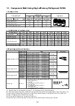
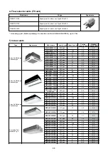
Страница 10: ... of the space constraint 2 Combination of outdoor units Model name Usage Appearance RBM BY53FE Indoor unit capacity code 1 Total below 6 4 RBM BY103FE Indoor unit capacity code 1 Total below 14 2 For 3 piping RBM BY53E Indoor unit capacity code 1 Total below 6 4 RBM BY103E Indoor unit capacity code 1 Total below 14 2 For 2 piping 5 RBM BY203FE Indoor unit capacity code 1 Total below 25 2 RBM BY303...

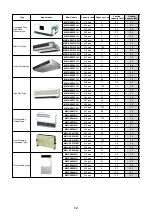
Страница 11: ... type 1 2 8 3 2 MMU AP0121WH 012 type 1 25 3 6 4 0 MMU AP0151WH 015 type 1 7 4 5 5 0 MMU AP0181WH 018 type 2 5 6 6 3 MMU AP0241WH 024 type 2 5 7 1 8 0 MMU AP0271WH 027 type 3 8 0 9 0 MMU AP0301WH 030 type 3 2 9 0 10 0 2 way Air Discharge Cassette Type MMU AP0481WH CHINA only 048 type 5 14 0 16 0 MMU AP0071YH 007 type 0 8 2 2 2 5 MMU AP0091YH 009 type 1 2 8 3 2 MMU AP0121YH 012 type 1 25 3 6 4 0 MM...

Страница 12: ... 1 2 8 3 2 MMK AP0121H 012 type 1 25 3 6 4 0 MMK AP0151H 015 type 1 7 4 5 5 0 MMK AP0181H 018 type 2 5 6 6 3 MMK AP0241H 024 type 2 5 7 1 8 0 MMK AP0072H 007 type 0 8 2 2 2 5 MMK AP0092H 009 type 1 2 8 3 2 High Wall Type MMK AP0122H 012 type 1 25 3 6 4 0 MML AP0071H 007 type 0 8 2 2 2 5 MML AP0091H 009 type 1 2 8 3 2 MML AP0121H 012 type 1 25 3 6 4 0 MML AP0151H 015 type 1 7 4 5 5 0 MML AP0181H 01...

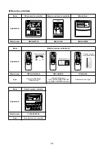
Страница 13: ...L SET GROUP CODE No UNITNo No R C TEST ZONE ALL ZONE GROUP SETTING 1234 SETDATA Name Appearance Model name Wired remote controller RBC AMT31E Simple wired remote controller RBC AS21E Weekly timer RBC EXW21E Name Appearance Model name Type Wireless remote controller kit RBC AX2U W E 4 way Air Discharge Cassette type RBC AX22CE Under Ceiling type 1 way Air Discharge Cassette type MMU AP 2SH Series T...

Страница 14: ...3 1 2 3 1 2 3 1 2 1 2 1 2 3 Fuse T6 3A 250V Fuse T3 15A 250V DC15V DC12V DC7V P301 BLK RED WHI WHI RED S N R L Power supply Single phase 220 240V 50Hz 220V 60Hz Indoor unit Earth screw DM FM Power supply circuit Motor drive circuit Parts name Fan motor Indoor temp sensor Temp sensor Temp sensor Temp sensor Louver motor Drain pump motor Float switch Drain control relay Pulse Motor Valve Color ident...

Страница 15: ... Power supply Single phase 220 240V 50Hz 220V 60Hz Indoor unit Earth screw Outdoor unit BLU BLU BLK BLK U1 U2 U1 Flow selector unit earth screw Power supply circuit CN01 WHI CN02 YEL Sub P C board MCC 1520 Symbol FM RC TR LM TA TC1 TC2 TCJ RY001 RY002 RY004 RY005 007 FS DM PMV Parts name Fan motor Running capacitor Transformer Louver motor Indoor temp sensor Temp sensor Louver control relay Drain ...

Страница 16: ...BLU BLU RED WHI BLK BLK U1 U2 U1 Power supply circuit Network adaptor P C board Symbol FM RC TR LM TA TC1 TCJ RY001 RY002 RY004 RY005 007 FS DM PMV Parts name Fan motor Running capacitor Power transformer Louver motor Indoor temp sensor Temp sensor Louver motor control relay Drain pump control relay Heater control relay Fan motor control relay Float switch Drain pump motor Pulse Motor Valve LM GRN...

Страница 17: ...1 CN101 BLK CN100 BRW 1 3 CN080 GRN TC2 PNL EXCT 2 1 CN073 RED 2 2 1 Filter CN070 WHI CN081 BLK 2 1 2 1 2 1 1 1 2 2 1 1 2 2 1 1 2 2 1 1 2 X Y 2 3 2 1 1 3 1 1 2 3 3 1 2 3 4 5 1 2 3 4 5 6 1 2 1 2 3 4 5 6 1 2 3 4 5 6 1 2 3 4 5 6 2 1 4 3 5 2 1 TC1 CN066 WHI AC IN CN044 BRW CN040 BLU Outdoor unit Remote controller Power supply single phase 220 240V 50Hz 220V 60Hz Indoor unit earth screw Closed end conn...

Страница 18: ...50Hz 220V 60Hz Indoor unit earth screw Closed end connector Flow selector unit earth screw 5 4 1 5 5 5 4 3 3 3 2 1 1 1 CN333 WHI Fuse T3 15A 250V CN82 BLU CN112 WHI CN111 WHI CN110 WHI CN71 CHK High ceiling setup LM CN33 WHI CN334 WHI FM 1 2 3 4 5 6 1 1 1 2 1 2 1 2 1 2 1 2 1 2 2 2 3 3 3 4 4 4 5 3 CN34 RED FS 1 2 3 1 3 4 5 1 2 3 4 5 1 2 3 4 5 1 2 3 4 5 5 5 6 6 6 PMV Motor drive circuit Fuse T6 3A 2...

Страница 19: ...50V DC15V DC12V DC7V P301 BLK RED WHI WHI WHI RED Wired remote controller 1 2 B A S N R L U2 1 2 CN1 WHI CN001 WHI Indoor unit power supply Single phase 220 240V 50Hz 220V 60Hz Indoor unit Earth screw WHI Outdoor unit BLK WHI BLK BLK BLU BLU BLK BLK TR WHI U1 U2 U1 DM Power supply circuit Motor drive circuit CN01 WHI CN02 BLU CN03 RED Network adaptor Option 1 2 1 2 1 2 1 2 X Y 3 3 2 2 1 1 Network ...

Страница 20: ... 2 3 1 2 3 1 2 3 1 2 1 2 TCJ CN102 RED 1 2 1 2 TA CN104 YEL FS CN030 RED 1 2 1 2 RY001 TR OC EMG RC Fuse T5 0A T10A 250V 1 2 3 1 2 3 CN309 YEL 1 2 3 1 2 3 RED WHI H M L UL 1 indicates the terminal block letter at inside indicates the terminal number 2 A dotted line and broken line indicate the wiring at site 3 indicates the control P C board 4 When attaching a drain pump exchange CN030 connector w...

Страница 21: ...A 250V Fuse T3 15A DC15V DC12V DC7V P301 BLK RED WHI Closed end terminal RED WHI Wired remote controller Outdoor unit 1 2 B A U2 U1 U2 U1 1 2 CN1 WHI CN001 WHI Indoor unit Earth screw WHI BLK BLK WHI BLK TR BLU WHI BLU BLK BLK DM FM Power supply circuit Motor drive circuit CN01 WHI CN02 BLU CN03 RED Network adaptor Option 1 2 1 2 1 2 1 2 X Y 3 3 2 2 1 1 Network adaptor P C board Color identificati...

Страница 22: ... 1 2 3 4 5 6 CN60 WHI 1 2 3 4 5 6 CN61 YEL 1 2 3 1 3 1 3 1 2 1 2 1 2 3 1 3 4 5 CN50 WHI CN41 BLU CN40 BLU GRY BLU BLU BLK BLK BLK WHI GRY CN309 YEL Option 1 2 CN32 WHI Fandrive CN82 BLU Motor drive circuit CN333 WHI CN334 WHI TC1 TC2 CN102 RED TCJ 2 1 2 1 2 1 2 1 2 1 2 1 CN104 YEL TA 1 1 3 3 1 2 3 4 5 6 1 1 1 2 3 4 5 6 1 2 3 4 5 6 1 2 3 4 5 6 2 2 3 4 4 5 5 1 3 5 1 3 1 2 3 1 2 3 5 PMV 1 1 5 4 5 4 L...

Страница 23: ... 15V DC 0V DC 12V DC 7V BLK HBS BLK CN22 F S CN82 BLU WHI 1 3 1 3 10 9 8 7 6 5 4 3 2 1 10 9 8 7 4 3 2 1 2 3 4 5 6 7 10 11 1 2 3 4 5 6 1 2 3 4 5 1 2 3 4 5 6 1 2 3 4 5 6 2 3 4 5 6 1 2 3 4 5 6 1 3 4 5 6 1 3 4 5 6 7 8 9 9 5 4 3 2 1 5 4 3 2 1 6 5 4 3 2 1 2 1 6 5 4 3 2 1 3 2 1 4 3 2 1 6 5 4 3 2 1 5 4 3 2 1 2 1 5 4 3 2 1 WHI WHI RED BRW YEL WHI BRW YEL GRY PNK GRY ORN RED BLU Infrared rays receive and in...

Страница 24: ...J 2 1 2 1 CN101 BLK CN100 BRN 1 3 CN080 GRN TC2 PNL EXCT 2 1 CN073 RED 2 2 1 3 2 4 5 1 Filter CN070 WHI CN081 BLK 2 1 2 1 2 1 1 1 2 2 1 1 2 2 1 1 2 X Y 2 3 2 1 1 3 1 1 2 3 3 1 2 3 4 5 1 2 3 4 5 6 1 2 1 2 3 4 5 6 1 2 3 4 5 6 1 2 3 4 5 6 1 2 3 4 5 6 1 2 3 4 5 6 1 2 3 4 5 6 1 2 3 4 5 6 2 1 TC1 2 1 2 1 CN066 WHI CN067 BLK AC IN RED WHI CN040 BLU Outdoor unit Remote controller Power supply single phase...

Страница 25: ...20V 60Hz Indoor unit earth screw Closed end connector CN01 WHI CN03 RED CN02 BLU CN03 RED CN041 BLU CN050 WHI CN061 YEL CN032 WHI Fan drive Option CN060 WHI EMG TR RED RED WHI WHI U1 U2 U1 U2 A B X Y Network adaptor Option Control P C board for undoor unit MCC 1403 MCC 1401 For AP0071BH AP0091BH AP0121BH 1 1 2 2 CN1 1 1 3 3 CN074 WHI CN075 WHI Power supply circuit TR 1 1 3 3 CN068 BLU FAN CN083 WH...

Страница 26: ...CJ 2 1 2 1 CN101 BLK CN100 BRW 1 3 CN080 GRN TC2 PNL EXCT 2 1 CN073 RED 2 2 1 Filter CN070 WHI CN081 BLK 2 1 2 1 2 1 1 1 2 2 1 1 2 2 1 1 2 2 1 1 2 X Y 2 3 2 1 1 3 1 1 2 3 3 1 2 3 4 5 1 2 3 4 5 6 1 2 1 2 3 4 5 6 1 2 3 4 5 6 1 2 3 4 5 6 2 1 4 3 5 2 1 TC1 CN066 WHI AC IN CN044 BRW CN040 BLU Outdoor unit Remote controller Power supply single phase 220 240V 50Hz 220V 60Hz Indoor unit earth screw Closed...

Страница 27: ... TC1 1 2 3 4 5 CN81 BLK 1 2 3 4 5 CN50 WHI CN309 YEL 1 2 3 4 5 CN60 WHI CN32 WHI Option 1 2 Fan drive 1 2 3 4 5 6 CN61 YEL CN41 BLU CN40 BLU CN44 BRW 1 2 3 4 5 6 1 1 2 2 1 1 2 3 3 BLU BLU BLK BLK 3 1 3 1 3 1 3 1 3 1 3 1 2 1 CN66 WHI WHI RED P301 CN67 BLK Motor drive circuit CN304 GRY RY302 CN68 BLU CN68 BLU Fuse T6 3A 250V Drain pump type SPH Type Non Drain pump type SH Type BLK RED WHI 2 1 Fuse T...

Страница 28: ...1 TE1 BLK BLK BLK CN505 GRN 2 1 2 1 TO BLK BLK BLK CN507 YEL 2 1 2 1 TL WHI BLK BLK CN521 WHI 2 1 2 2 2 1 Option board 3 1 3 4 4 1 CN600 WHI T6 3A FUSE CN325 YEL Option CN400 WHI CN305 RED ORN BLK BLK ORN CN307 WHI RY521 RY511 CN401 WHI RED PNK RED BLU WHI BLK CN402 2 2 5 5 5 3 1 3 1 7 7 5 4 4 3 3 3 2 2 1 3 1 3 1 4 3 2 1 2 1 1 1 T6 3A FUSE T6 3A FUSE RED WHI BLK GRY CN317 BLU CN323 WHI 4 4 3 3 2 2...

Страница 29: ... 1 1 1 1 3 3 4 5 2 1 3 5 1 2 3 4 RBM Y1802FE only RBM Y2802FE only RBM Y2802FE only Earth screw WHI ORN BLU YEL BRW CN10 WHI CN01 RED Control P C board MCC 1431 CN02 GRN CN81 BLK Supplied wire Power supply Supplied wire Control wiring Control P C board for indoor unit CN67 BLK Power supply single phase 220 240V 50Hz Indoor unit earth screw Indoor unit Flow Selector unit ...

Страница 30: ...tor panel MP24GA 2 way Air Discharge Cassette Type Model MMU AP 0071WH 0091WH 0121WH 0151WH 0181WH Fan motor AF 230 53 4G AF 230 39 4B Running capacitor for fan motor AC 400V 1 0µF AC 450V 2 0µF Drain pump motor PJD 05230TF 1 Float switch FS 0208 608 Control P C board transformer TT 13 Pulse motor EDM MD12TF 3 Pulse motor valve EDM B25YGTF EDM B40YGTF TA sensor Lead wire length 268mm TC1 sensor Ø4...

Страница 31: ...TC1 sensor Ø4 size lead wire length 1200mm Vinyl tube Blue TC2 sensor Ø6 size lead wire length 1200mm Vinyl tube Black TCJ sensor Ø6 size lead wire length 1200mm Vinyl tube Red Concealed Duct Standard Type Model MMD AP 0071BH 0091BH 0121BH 0151BH 0181BH Fan motor ICF 280 120 2 Drain pump motor ADP 1409 Float switch FS 0218 102 Pulse motor EDM MD12TF 3 Pulse motor valve EDM B25YGTF EDM B40YGTF TA s...

Страница 32: ...Black TCJ sensor Ø6 size lead wire length 1200mm Vinyl tube Red SPH series only Under Ceiling Type Model MMC AP 0151H 0181H 0241H 0271H 0361H 0481H Fan motor SWF 280 60 1 SWF 280 60 2 SWF 280 120 2 Louver motor MP24GA1 Pulse motor EDM MD12TF 3 Pulse motor valve EDM B40YGTF EDM B60YGTF 1 TA sensor Lead wire length 155mm Vinyl tube TC1 sensor Ø4 size lead wire length 1200mm Vinyl tube Blue TC2 senso...

Страница 33: ... 5µF AC450V 1µF AC450V 2µF Transformer TT 13 Pulse motor EDM MD12TF 3 Pulse motor valve EDM B25YGTF EDM B40YGTF TA sensor Lead wire length 818mm Vinyl tube TC1 sensor Ø4 size lead wire length 2000mm Vinyl tube Blue TC2 sensor Ø6 size lead wire length 2000mm Vinyl tube Black TCJ sensor Ø6 size lead wire length 2000mm Vinyl tube Red Floor Standing Type Model MMF AP 0151H 0181H 0241H 0271H 0361H 0481...

Страница 34: ... DC42V 1A 6P Inductor CH 44FK 1 45mH 25A Smoothing condenser For compressor 400LRSN 1500M 1500µF 400V Power supply transformer TT 01 03T AC230V 350mA P C board Noise filter MCC 1366 FKX 240NK 4810US 0 48mH 30A MCC 1366 P C board Line filter AC FKX 220NK 6310US 0 63mH 25A MCC 1366 P C board P C board Control board MCC 1429 P C board IPDU for compressor IPDU 4T62DA1E 6 2kW MCC 1502 P C board Power s...

Страница 35: ...alve SV3D valve SV11 valve SV6 valve SV42 valve SV41 valve High pressure SW1 High pressure SW2 TD1 sensor TD2 sensor SV3A valve SV3B valve TL sensor TO sensor TE sensor Check joint Low pressure Check joint High pressure Check joint Liquid pipe SV5 valve TS1 sensor SV12 valve PMV 4 way valve High pressure sensor Front side Rear side ...

Страница 36: ...DENo UNIT No TEST SETTING DATA SET R C No H C TEST SETTING WEEKLY TIMER ERROR SuMoTuWeTh Fr Sa PROGRAM1 PROGRAM2 PROGRAM3 SELECT ZONE CL SET GROUP CODE No UNITNo No R C TEST ZONE ALL ZONE GROUP SETTING 1234 SETDATA Concealed Duct Type Concealed Duct High Static Pressure Type Slim Duct Type Under Ceiling Type High Wall Type MMK AP0071H to AP0241H MMK AP0072H to AP0122H Air outlet flange Discharge d...

Страница 37: ...swing display Indicates the movement of the louver 10 Setpoint temperature display The selected set up temp is displayed 11 Remote controller sensor display Displayed while the sensor of the remote controller is used 12 PRE HEAT display Displayed when the heating or defrost operation is carried out While this indication is displayed the indoor fan stops or the runs in LOW fan speed 13 Operation re...

Страница 38: ...in the order shown on the right DRY mode function is not available on the Concealed Duct High Static Pressure Type 3 Select air volume with FAN button One push of the button and the display changes in the order shown on the right When air volume is AUTO air volume differs according to the temperature difference between the set temperature and the room temperature In DRY mode AUTO is displayed and ...

Страница 39: ... with horizontal set point In Heating operation Use the discharge louver with downward set point How to set up the air direction Push SWING FIX button 1 Every push of the button the air direction changes In Heating operation Set the air outlet louver downward If directing it upward the hot air may not reach the floor In Cooling Dry operation Set the air outlet louver upward If directing it downwar...

Страница 40: ...o display Unit No 1 2 Unit No 1 4 Unit No 1 3 Under Ceiling Type 1 way Air Discharge Cassette Type 2SH Series When the air conditioner is stopped the horizontal louver Up Down air direction adjustment plate automatically directs upward When the air conditioner is in stand by status waiting to heat the horizontal louver Up Down air direction adjustment plate directs upward The swinging operation st...

Страница 41: ...ontal louver using the SWING FIX button on the remote controller The horizontal louver will not stop immediately even if the switch is pushed Note pushing the switch again when the required louver direction has been reached will stop the louver Adjustment of air Flow direction rightwards leftwards To change the air outlet direction to the right or left side set the vertical louver located behind t...

Страница 42: ...er in the desired posi tion 3 Swing button UNIT To set up the air flow the direction individu ally push the UNIT button to display each indoor unit No in a group control Then set up the air flow direction to the desired indoor unit If there is no display all the indoor units can be operated collectively Every push of the UNIT button will change the display as shown in the figure 1 2 In this case d...

Страница 43: ...rect capacity Fuses are used Using wire or copper wire may cause a fire or unit fault Ensure that the power supply to the unit is exclusive and is the correct rated voltage To disconnect the appliance from the main power supply This appliance must be connected to the main power supply by means of a circuit breaker or a switch with a contact separation of at least 3mm 3 12 Maintenance Cleaning of a...

Страница 44: ...e air inlet grille If the FILTER lamp on the indoor unit is lit push the FILTER button on the remote controller or the TEMPO RARY button on the indoor unit to turn off the lamp Cleaning of main unit remote controller CAUTION Wipe them with a soft and dry cloth A cloth dampened with cold water may be used on the indoor unit if it is very dirty Never use a damp cloth on the main unit or remote contr...

Страница 45: ...lure occurs during operation all operations will stop When restarting the unit push the ON OFF button again Fan rotation of stopped unit When other indoor units within the same system are in operation the fan on the indoor units that are on stand by will rotate to protect the machine once per approximately 1 hour for several minutes Protective device High pressure switch The high pressure switch w...

Страница 46: ...ximum cooling and heating specifications Outdoor temp DB 10 C Cooling mode 21 C Heating mode Silent It s strange 3 15 When the Following Symptoms are Found Check the points described below before contacting your local service repair center Symptom Outdoor unit White misty cold air or water is blown out Sometimes the noise Pushu is heard Indoor unit Swish sound is sometimes heard Slight Pishi sound...

Страница 47: ...IMER SET Procedure 1 2 3 Description When pushing the SET and TEST buttons at the same time for 4 seconds or more the following display will appear If Service check is displayed the mode enters into the change error history mode 01 Order of error history is displayed in CODE No window Check code is displayed in CHECK window Indoor unit address in which the error has occurred is displayed in UNIT N...

Страница 48: ...ck joint High pressure sensor High pressure switch High pressure switch Oil separator Check valve Check valve Check valve Check valve Strainer Sensor TK1 Sensor TK4 Sensor TK3 Capillary tube Capillary tube Strainer Capillary tube Strainer Strainer Strainer Strainer Strainer Capillary tube Capillary tube Solenoid valve SV42 Check valve Check valve Capillary tube Check valve Compressor 2 Inverter Co...

Страница 49: ...nnector CN317 Blue 1 Cooling Heating selection 2 Reverse defrost 3 Main Sub heat exchanger selection PMV1 2 Connector CN300 301 White 1 Super heat control function during all heating operation and mainly heating partly cooling operation 2 Under cool adjustment function during all cooling operation 3 Divided flow control function during mainly cooling partly heating operation Pulse motor valve PMV3...

Страница 50: ...ase heater Connector CN321 Red 1 Prevents liquid accumulation to accumulator Balance pipe 1 Oil balancing pipe between outdoor unit This unit does not use this Balance pipe Operation mode Operation mode Outline 1 All Indoor Unit s Operating for Cooling Only cooling operation without heating operation Outdoor heat exchanger Main heat exchanger is used as a condenser 2 All Indoor Unit s Operating fo...

Страница 51: ... To indoor liquid side Strainer Capillary tube Capillary tube Capillary tube SVS Configuration of outdoor unit heat exchanger Flow Selector Unit FS Unit RBM Y1122FE Front side Right Rear side Left Main heat exchanger Fan motor Wind Sub heat exchanger Wind Sub heat exchanger Propeller fan RBM Y1802FE RBM Y2802FE Functional part name Solenoid valve SVD SVS SVDD SVSS Functional outline Discharge gas ...

Страница 52: ... indoor suction temperature Connector CN100 3P Brown 1 Controls PMV super heat in cooling operation Connector CN101 2P Black 1 Controls PMV under cool in heating operation Connector CN102 2P Red 1 Controls PMV super heat in cooling operation 2 MMU AP0071 to AP0121YH only Controls PMV under cool in heating operation Air heat exchanger at indoor side Fan M Fan motor Sensor TA Sensor TC1 Gas side Liq...

Страница 53: ... continues OFF à ON Stop Once OFF à ON Mainly cooling partly heating cooperation ON Operation continues ON à OFF Operation continues As ON Operation continues As ON Mainly heating partly cooling operation ON Stop Once ON à OFF Operation continues As ON Operation continues As ON Before update All heating operation ON Stop Once ON à OFF Operation continues As ON Operation continues As ON Outline of ...

Страница 54: ...nverter Compressor 1 Inverter TK2 TD2 TD1 Liquid tank Oil tank PMV1 PMV2 PMV3 Main heat exchanger OS ST ST SVD SVS SVDD SVSS Cooling FS unit Indoor unit TCJ TC2 TC1 PMV ST ST SVD SVS SVDD SVSS Cooling TCJ TC2 TC1 PMV ST ST SVD SVS SVDD SVSS Cooling TCJ TC2 TC1 PMV ST ST SVD SVS SVDD SVSS Stop TCJ TC2 TC1 PMV Header unit Suction gas pipe Discharge gas pipe Liquid pipe High pressure gas or condensed...

Страница 55: ...er TK2 TD2 TD1 Liquid tank Oil tank PMV1 PMV2 PMV3 Main heat exchanger OS ST ST SVD SVS SVDD SVSS Cooling FS unit Indoor unit TCJ TC2 TC1 PMV ST ST SVD SVS SVDD SVSS Cooling TCJ TC2 TC1 PMV ST ST SVD SVS SVDD SVSS Cooling TCJ TC2 TC1 PMV ST ST SVD SVS SVDD SVSS Stop TCJ TC2 TC1 PMV Suction gas pipe Discharge gas pipe Liquid pipe Header unit FM Sensor TO TS1 TS2 TL Main heat exchanger SV2 SV12 TE1 ...

Страница 56: ...r 2 Inverter Compressor 1 Inverter TK2 TD2 TD1 Liquid tank Oil tank PMV1 PMV2 PMV3 Main heat exchanger OS ST ST SVD SVS SVDD SVSS Heating FS unit Indoor unit TCJ TC2 TC1 PMV ST ST SVD SVS SVDD SVSS Heating TCJ TC2 TC1 PMV ST ST SVD SVS SVDD SVSS Heating TCJ TC2 TC1 PMV ST ST SVD SVS SVDD SVSS Stop TCJ TC2 TC1 PMV Suction gas pipe Discharge gas pipe Liquid pipe Header unit FM Sensor TO TS1 TS2 TL M...

Страница 57: ...K4 TK3 SV42 HP HP Compressor 2 Inverter Compressor 1 Inverter TK2 TD2 TD1 Liquid tank Oil tank PMV1 PMV2 PMV3 Main heat exchanger OS ST ST SVD SVS SVDD SVSS Cooling FS unit Indoor unit TCJ TC2 TC1 PMV ST ST SVD SVS SVDD SVSS Cooling TCJ TC2 TC1 PMV ST ST SVD SVS SVDD SVSS Stop TCJ TC2 TC1 PMV ST ST SVD SVS SVDD SVSS Heating TCJ TC2 TC1 PMV Suction gas pipe Discharge gas pipe Liquid pipe Operating ...

Страница 58: ... Pd sensor Pd sensor TK1 TK4 TK3 SV42 HP HP Compressor 2 Inverter Compressor 1 Inverter TK2 TD2 TD1 Liquid tank Oil tank PMV1 PMV2 PMV3 Main heat exchanger OS ST ST SVD SVS SVDD SVSS Heating FS unit Indoor unit TCJ TC2 TC1 PMV ST ST SVD SVS SVDD SVSS Heating TCJ TC2 TC1 PMV ST ST SVD SVS SVDD SVSS Stop TCJ TC2 TC1 PMV ST ST SVD SVS SVDD SVSS Cooling TCJ TC2 TC1 PMV Suction gas pipe Discharge gas p...

Страница 59: ...anger OS ST ST SVD SVS SVDD SVSS Cooling FS unit Indoor unit TCJ TC2 TC1 PMV ST ST SVD SVS SVDD SVSS Heating TCJ TC2 TC1 PMV ST ST SVD SVS SVDD SVSS Heating TCJ TC2 TC1 PMV ST ST SVD SVS SVDD SVSS Stop TCJ TC2 TC1 PMV Suction gas pipe Discharge gas pipe Liquid pipe TS1 4 Way valve OFF Header unit Follower unit FM FM Sensor TO TS2 TL Main heat exchanger SV2 SV12 TE1 SV5 SV41 SV3A SV3E SV3B SV3D SV6...

Страница 60: ... HEAT AUTO operation Heating operation is automatically selected with difference between the set point temperature and room temperature 1 Set point temperature adjustment range on remote controller C Wired type Wireless type Allcooling 18 to 29 C 18 to 30 C All heating 18 to 29 C 16 to 30 C 2 The set point temperature in heating operation can be offset using item code DN 06 Setup data Setup temp c...

Страница 61: ...hen 1 zone is detected the timer is cleared and the operation returns to the normal operation When the command frequency became S0 with continua tion of J zone operation of the the indoor fan in LOW mode until it reaches the 1 zone It is reset when the following conditions are satisfied Reset conditions 1 TC1 12 C and TC2 12 C and TCJ 12 C 2 30 minutes passed after stop 2 In all cooling operation ...

Страница 62: ...ff by changing the set up temp the thermostat is OFF with even the above condition The protective control has priority 1 During COOL operation including DRY operation the drain pump operates 2 While the drain pump operates if the float switch works the drain pump continues operation and a check code is displayed 3 While the drain pump stops if the float switch works turn off the capacity demand co...

Страница 63: ...tion the fan rotates with lower air speed than one specified in order to prevent discharge of cold draft or stops including case that defrost operation is being performed HEAT operation cannot be performed because COOL priority is set Outdoor I F P C board SW11 bit 1 is ON and the other indoor unit is under COOL DRY operation 2 HEAT standby is displayed until the above conditions are released 1 Th...

Страница 64: ...3 opening is controlled according to the demand capacity difference HP between the cooling capacity and the total heating capacity 3 The PMV will be fully closed when the system is in Standby or No demand modes and when a mal function in the system has occurred 1 Fan control in all cooling operation 1 The outdoor fan speed mode is determined by the detected Pd pressure value 2 When cooling operati...

Страница 65: ...uccessive operation 1 Measurement of sensors TK1 to TK4 is used to determine whether the correct amount of oil is present in the compressor case 2 A comparison of measurements taken from TK1 TK2 with that of TK3 TK4 is used to judge whether there is sufficient oil in the compressor case If there is insufficient oil in the compressor case the system switches to the oil equalizing control method 3 T...

Страница 66: ... control is executed approxi mately every hour 2 The period of recovery lasts for approximately 2 to 10 minutes though this is dependent upon the load condition 3 Control for refrigerating whilst oil recovery in simultaneous operation This function is executed to recover the refrigerating oil accumulated in the low pressure gas inter unit piping regardless of all cooling operation all heating oper...

Страница 67: ... SV42 when PS pressure 0 24MPa and Pd pressure 2 2MPa 2 High pressure release control This function is for gas bypass control which emergently prevents the high pressure cut Turn on SV41 and SV42 when Pd pressure 3 5MPa and turn off SV41 and SV42 when Pd pressure 3 45MPa 5 SV6 valve 1 Cooling bypass control This function is a liquid refrigerant bypass control to suppress the rise of the discharge ...

Страница 68: ...in controls of the IPDU P C board are 1 Current release control Feedback from the AC input current sensor CT is used to prevent the inverter input current exceeding its specified limit 2 Heat sink temperature detection control Feedback from the thermistor TH on the compressor driving module is used to prevent the IGBT from overheating The highest value is taken from IPDU 1 and IPDU 2 TH sensors 3 ...

Страница 69: ...se this sound may not be noticeable 2 Do not remove the driving part head of the PMV during operation as it may cause the PMV to malfunction 3 When transporting or replacing the outdoor unit never keep the driving part head removed from the PMV body as the valve will be closed and may result in damage or failure due to sealed liquid compression 4 When refitting the driving part head to the body of...

Страница 70: ... 2 Inverter Compressor 1 Inverter TK2 TD2 TD1 Liquid tank Oil tank PMV1 PMV2 PMV3 Main heat exchanger OS Header outdoor unit MMY MAP1202FT8 FM Sensor TO TS1 TS2 TL Main heat exchanger SV2 SV12 TE1 SV5 SV41 SV3A SV3E SV3B SV3D SV6 SV11 SV3C 4 Way valve OFF Accumulator Pd sensor Pd sensor TK1 TK4 TK3 SV42 HP HP Compressor 2 Inverter Compressor 1 Inverter TK2 TD2 TD1 Liquid tank Oil tank PMV1 PMV2 PM...

Страница 71: ...umbers in the group control are successively displayed In this time the fan of the selected indoor unit only is turned on 3 Specify the item code DN using the setup temperature and buttons 4 Select the setup data using the timer time and buttons When selecting the DN code to 33 change the temperature indication of the unit from C to F on the remote controller 5 Push SET button OK if display goes o...

Страница 72: ...tte to 0037 0000 Unfixed 0001 to 0034 0001 No 1 unit to 0030 No 30 unit 0001 No 1 unit to 0064 No 64 unit 0000 Individual 0001 Header unit of group 0002 Follower unit of group 0000 Not provided 0001 Swing only 0004 4 way Air Discharge Cassette type and Under Ceiling type 0000 0 deg to 0010 10 deg For setup temperature reversal of COOL HEAT by Data value 2 0000 None 0001 Restart 0000 Usual 0001 Con...

Страница 73: ...et Floor Standing Concealed Floor Standing Abbreviated Model name MMU AP XXX SH MMU AP XXX H MMU AP XXX WH MMU AP XXX YH MMD AP XXX BH MMD AP XXX SPH SH MMD AP XXX H MMC AP XXX H MMK AP XXX H MML AP XXX H MML AP XXX BH MMF AP XXX H Setup data 0001 0003 0005 0007 0009 0011 0012 0013 0015 0017 0018 0021 0023 Model 007 009 012 015 018 024 027 030 036 048 056 072 096 Setup data 0000 0001 0002 0003 000...

Страница 74: ... changes according to the indoor unit model In group control the firstly displayed indoor unit No becomes the header unit Each pushing of the UNIT button changes the indoor unit number within the group Select the indoor unit that requires setup The indoor unit selected can be confirmed at this time as the louver and fan will operate Use and buttons of the set temperature to specify the item code 0...

Страница 75: ...nit it is necessary to set up the Item code This should be done after the addressing of the units When connecting multiple indoor units to a single FS unit only group control is available Remote controllers cannot be connected to individual units n Usage Features It is not possible to group control indoor units that are connected to more than one FS unit Indoor units off of a single FS unit cannot...

Страница 76: ...ation Thermo ON Cooling operation Thermo OFF FS unit SVS SVD SVSS Suction gas pipe Liquid pipe Discharge gas pipe SVDD Indoor unit Control wiring between indoor unit and FS unit SVD SVDD SVS SVSS OFF OFF OFF ON n In case of not setting 01 to Item code 0E When more than one indoor unit has been set up as a group to one FS unit and you have forgotten to set 01 on Item code 0E on all the indoor units...

Страница 77: ...ation signal Output during normal operation 3 Error signal Output during alarm Serial communication error or indoor outdoor protective device operation 2 Wiring diagram using remote control interface TCB IFCB 4E Input IFCB 4E No voltage ON OFF serial signal Output No voltage contact for operation error display Contact capacity Below Max AC240V 0 5A 1 2 3 4 5 6 CN61 T10 YEL 1 2 3 4 1 2 3 4 5 6 CN13...

Страница 78: ...the indoor unit numbers in group control are displayed succes sively In this time the fan of the selected indoor unit only turns on 3 Using the setup temp or button specify the item code 4 Using the timer time or button select the setup data At shipment The setup data are as follows Setup data Handling of operation of air to air heat exchanger or ventilating fan Unavailable At shipment Available 1...

Страница 79: ...at card is taken out from the card switch box When the card switch box does not perform the above contact operation convert it using a relay with b contact 2 Operation Handle the wired remote controller switch in the following procedure Use the wired remote controller switch during stop of the system 1 Push concurrently SET CL TEST buttons for 4 seconds or more 2 Using the setup temp or button spe...

Страница 80: ...nit n Setup Turn Bit 2 of the dip switch SW10 on the interface P C board of the outdoor unit to ON n Specifications The outdoor fan high static pressure shift function increases the fan speed on the outdoor unit to enable a discharge duct to be installed on the discharge port the design of the ducting should be such that a static pressure of 35 Pa is not exceeded This function should be executed w...

Страница 81: ...ion selection CN508 Red CN509 Black CN510 White CN513 Blue CN511 Green Connector position detail Switch position detail No 1 2 3 4 5 6 Function Power peak cut control Standard Power peak cut control Expansion Snowfall fan control External master ON OFF control Night operation control Operation mode selection control Switch No SW07 SW07 Bit 1 1 2 Connector No CN513 CN513 CN509 CN512 CN508 CN510 Use...

Страница 82: ...e P C board Connector position detail Switch position detail Operation The upper limit capacity of the outdoor unit is restricted based on the demand request signal from outside L1 Display lamp during power peak cut control SW1 Power peak cut ON switch ON during demand OFF in normal time 1 SW2 Power peak cut OFF switch OFF during demand ON in normal time 1 1 Input signals of SW1 and SW2 are accept...

Страница 83: ... cut OFF switch 1 1 Input signals of SW1 and SW2 are acceptable even if they are upper than pulse input 100mm sec or serially made Be sure to prepare a contact for each terminal Relay contact capacity of operation port Below AC240V 1A COSØ 100 Below DC24V 2A Non inductive load Note When connecting non inductive load such as relay coil to L1 load insert the noise surge absorber CR In case of AC or ...

Страница 84: ...terminals concurrently 2 Be sure to prepare a contact for each terminal Outside signal No voltage pulse contact External master ON OFF control board TCB PCMO 2E Outdoor unit destination to be connected becomes the header outdoor unit U1 SMC Input signal for start SMH Input signal for stop Terminal COOL SMC Heat SMH Input signal ON OFF ON OFF Operation Starts collectively indoor units Stops collect...

Страница 85: ...ure to prepare a contact for each contact terminal Outside signal No voltage serial contact SMC COOL mode designated input switch SMH HEAT mode designated input switch External master ON OFF control board TCB PCMO 2E Outdoor unit destination to be connected becomes the header outdoor unit U1 CN508 4P RED Header outdoor unit interface P C board Connection cable External master ON OFF control board ...

Страница 86: ... U2 U1 A U2 U5 U6 U4 Header unit A U1 U3 U2 U5 U6 U4 Follower unit B U1 U3 U2 U5 U6 U4 Follower unit C Outdoor unit Indoor unit To indoor unit Central control units Other refrigerant line Other refrigerant line Earth 3 phase 380 415V Leak interception Main switch 1 phase 230V Leak interception Main switch B Remote controller U1 A U2 B Remote controller U1 A U2 B Remote controller U1 A U2 B 1 2 5 3...

Страница 87: ...et ports After pressure test check that the pipework and indoor units have been vacuumed and the correct amount of additional gas has been charged Are valves of all the outdoor units fully opened Suction gas side Discharge gas side Liquid side Balance side Header unit A XXXX XXXX XXXX XXXX Follower unit B XXXX XXXX XXXX XXXX Follower unit C XXXX XXXX XXXX XXXX Check list 2 Calculate the additional...

Страница 88: ...02 SW03 7 segment display B 8 4 Address Setup After power ON set up the indoor address from the interface P C board of the outdoor unit The address setup operation cannot be performed by power ON only 8 4 1 Cautions 1 It requires approx 5 minutes usually for 1 line to automatically set up address However in some cases it may require maximum 10 minutes 2 It is unnecessary to operate the air conditi...

Страница 89: ...emote controller Central remote controller Outdoor Indoor Indoor Remote controller Central remote controller Outdoor Indoor Indoor Remote controller Remote controller Outdoor Indoor Indoor Remote controller Central remote controller REQUIREMENT When a group control is performed over the multiple refrigerant lines be sure to turn on the power supplies of all the indoor units connected in a group at...

Страница 90: ...e controller U3 U4 U1 U2 U5 U6 U1 U2 A B Follower unit U3 U4 U1 U2 U5 U6 U1 U2 A B Remote controller Relay connector Relay connector Open ON 1 2 1 2 3 3 1 Header unit Follower unit Follower unit Header unit Header unit ON Open Open Setup is unnecessary Setup is unnecessary OFF after address setup OFF after address setup Setup is unnecessary Setup is unnecessary Outdoor interface P C board 2 1 SW30...

Страница 91: ... the same refrigerant line can be confirmed An outdoor unit is selected the indoor unit numbers in the same refrigerant line are successively displayed and then its indoor unit fan is turned on 1 Push the timer time TEST buttons simultaneously for 4 seconds or more Firstly the line 1 item code Address Change is displayed Select outdoor unit 2 Using UNIT SWING FIX buttons select the line address 3 ...

Страница 92: ... up to line address indoor address and group address data from the remote controller For the setup procedure refer to the abovementioned address setup from the remote controller Method 2 Clear the indoor addresses in the same refrigerant line from the outdoor unit 1 Turn off the power of the refrigerant line to be returned to the status at shipment and change the header unit to the following statu...

Страница 93: ...B Header unit Remote controller U3 U4 U1 U2 U5 U6 U1 U2 A B Follower unit Remote controller U3 U4 U1 U2 U5 U6 U1 U2 A B Remote controller U3 U4 U1 U2 U5 U6 U1 U2 A B Follower unit U3 U4 U1 U2 U1 U3 U2 U4 U5 U6 U1 U2 A B Remote controller Center unit Center unit Header unit Header unit Central control device Added indoor unit 8 4 4 Check after Address SetupWhen Central Control System is Connected W...

Страница 94: ...ndition that a normal operation can be performed Exceeded No of connected indoor units or exceeded capacity Duplication of outdoor addresses Only when outdoor address was manually set up Duplication of outdoor line addresses Line address setup error occurred after connec tion between U1 U2 and U3 U4 connectors Duplicated of indoor units with priority There are two or more indoor units set up with ...

Страница 95: ... follower unit in the individual control Unit which does not response to remote controller The power is not turned on Unit which is not displayed on remote controller Remote controller is not connected with cable Unit which is not displayed on remote controller Miscabling of remote controller Unit which is not displayed on remote controller Remote controller communication circuit error Unit which ...

Страница 96: ...U1 U2 U5 U6 Indoorunit Header unit U5 U6 Indoorunit Indoorunit U1 U2 U3 U4 U5 U6 Header unit U5 U6 U1 U2 Follower unit Indoorunit U1 U2 U3 U4 Incorrect wiring example Fig 1 Remote controller status No response Header unit 7 segment display E19 00 Incorrect example Fig 2 Remote controller status No response Header unit 7 segment display E19 02 Incorrect example Fig 3 Remote controller status No res...

Страница 97: ...roller and outdoor interface P C board 1 Test operation start stop operation Test operation from remote controller Wired remote controller 1 When pushing TEST button for 4 seconds or more TEST is displayed in the display section and the mode enters the test operation mode 2 4 3 1 5 ON OFF FAN TEMP SWING FIX TIME MODE VENT UNIT SET CL FILTER RESET TEST TIMER SET TEST TEST 2 Push ON OFF button 3 Usi...

Страница 98: ...e the adjust corner cap and the attached with sensor section from the ceiling panel For removal method follow to the installation instructions attached to the ceiling panel Be careful to handling the sensor section because cables are connected to the sensor Remove the sensor cover from the adjust corner cap 1 screw 2 Change Bit 1 TEST of the switch S003 on the sensor P C board from OFF to ON Mount...

Страница 99: ...utton After checking the receiving sound Pi immediately After checking the receiving sound Pi immediately push Temperature set button to set to 19 C push Temperature set button to set to 29 C After checking the receiving sound Pi immediately After checking the receiving sound Pi immediately push Temperature set button to set to 18 C push Temperature set button to set to 30 C Then repeat the proced...

Страница 100: ...eck operation status of the compressor Is air circulation good Is the operating current normal Is the operating pressure normal Check direction of the louver Execute a test operation using Function of start stop the indoor unit from outdoor unit in Service support function Check power voltage of the main power supply Check cable size of the power supply Check temperature load of the indoor room ou...

Страница 101: ...ssette type air conditioners connected Data changes according to installed pipe length combination of indoor units or connected indoor capacity For a compressor the left side is 1 and the right side is 2 viewed front the front of the unit Even if two compressors operate the frequency difference may set as a measures against resonance The temperature of indoor heat exchanger TC indicates TCJ sensor...

Страница 102: ...g status Stops the specified indoor unit Note The other indoor units keep existing status Operates the specified indoor unit Note The other indoor units keep existing status Setup Release Setup Push SW04 for 2 seconds or more with SW01 2 SW02 5 SW03 1 Release Return SW01 SW02 SW03 to 1 Setup Push SW04 for 2 seconds or more with SW01 2 SW02 6 SW03 1 Release Return SW01 SW02 SW03 to 1 Setup Push SW0...

Страница 103: ...ion check Stop End Interface P C board 7 segment display A 7 segment display B SW04 SW05 SW01 SW02 SW03 Rotary switch 2 All heating test operation function This function is provided to change collectively the mode of all the indoor units connected to the same system for heating test operation mode using switches on the interface P C board of the outdoor unit Operation procedure NOTE The test opera...

Страница 104: ...the operation continues in the current mode FAN COOL HEAT Set on the interface P C board of the header unit SW01 to 2 Sw02 to 7 and SW03 to 1 respectively CH is displayed on 7 segment display A Push SW04 on the interface P C board of the header unit for 2 seconds or more The indoor unit to be started operates After test operation return the rotary switches SW01 SW02 and SW03 on the interface P C b...

Страница 105: ... the interface P C board of the header unit for 2 seconds or more If pushing this switch continuously for 10 seconds or more the operation changes to the individual test operation The indoor unit to be started operates Push the push switch SW05 on the interface P C board of the header unit for 2 seconds or more 7 segment display A Address display of corresponding indoor unit B 00 is displayed for ...

Страница 106: ...nds or more 2 Using buttons set FF to item code The display in Section A in the following figure is counted with interval of 5 seconds as When the count arrives the error is cleared However counting from is repeated on the display 3 When TEST button is pushed the status returns to the normal status Error clearing in indoor unit Error in the indoor unit is cleared by ON OFF button on the remote con...

Страница 107: ...of both the outdoor and the indoor units are once cleared Method 1 Be sure to reset power of both the outdoor and the indoor units NOTE After power reset it requires usually 3 minutes to power on due to the initial communication of the system In same cases it requires Max 10 minutes Set the rotary switches on the interface P C board of the header unit to the following setting SW01 2 SW02 16 SW03 1...

Страница 108: ...e P C board of the header unit as follows SW01 2 SW02 4 SW03 1 7 segment display A A 1 B 7 segment display A A 1 A FF Push the push switch SW04 on the interface P C board of the header unit for 2 seconds or more display of the connected remote controller flashes Push the push switch SW05 on the interface P C board of the header unit for 2 seconds or more Operation Check the connected remote contro...

Страница 109: ...shown on 7 segment display for one minute as follows P 00 Clear After 2 minutes 1 minutes for Close fully have passed when setup has finished the PMV automatically returns to the normal operation 8 7 5 Pulse Motor Valve PMV Forced Open Fully Close fully Function in Outdoor Unit This function is provided to fully open or close fully the P M V PMV1 PMV2 PMV3 used in the outdoor unit for 2 minutes I ...

Страница 110: ...lenoid valve is as below NOTE 1 Be aware that there is a 5 second delay in the operation of the selected solenoid valve after SW02 has been set NOTE 2 The mark in the table indicates the selected solenoid valve is forced on NOTE 3 The mark in the table indicates the selected solenoid mode will depend on the specifications of the air conditioner NOTE 4 The mark in the table indicates the selected s...

Страница 111: ...3 From when fan step 31 is displayed in 7 segment display B the fan starts operation Max step operation 4 After then 7 segment display B and the fan step are changed by changing the setup number of the switches SW02 and SW03 Output pattern of the fan is as follows Clear This function is cleared by one of the following operations 1 When SW01 setting number was changed to other number 2 Push switch ...

Страница 112: ... the header unit are set to 1 2 Push the push switch SW04 for 2 seconds or more 3 E 1 is displayed on 7 segment display A 4 The fan of the outdoor unit in which error occurred starts operation within approx 10 seconds when E 1 was displayed In case to operate the fans in all the normal outdoor units 1 Check all the switches SW01 SW02 and SW03 on the interface P C board are set to 1 1 1 2 Push the ...

Страница 113: ...e fix manual mode 3 As shown in the following table TO sensor value can be fixed by setting the rotary switch SW02 on the interface P C board SW01 SW02 SW03 7 segment display B TO sensor value SW01 SW02 SW03 7 segment display B TO sensor value 1 10 10 C 9 45 45 C 2 15 15 C 10 15 15 C 3 20 20 C 11 10 10 C 4 25 25 C 12 5 5 C 5 30 30 C 13 0 0 C 6 35 35 C 14 2 2 C 7 40 40 C 15 5 5 C 2 8 15 43 43 C 2 1...

Страница 114: ...ening again Clear Open CHK pin If the system is operating it stops once but automatically restart after several minutes For the details of CHK pin CN71 on indoor P C board and DISP pin CN72 on indoor P C board refer to 11 Control circuit configuration Indoor unit 2 Indoor P C board MCC 1402 and MCC 1403 8 7 11 Indoor Fan Only Operating Mode When operating an air conditioner with indoor units and r...

Страница 115: ...r suction temp TA Indoor coil temp TCJ Indoor coil temp TC2 Indoor coil temp TC1 Indoor discharge temp Tf NOTE 1 Indoor PMV opening No of connected indoor units Total HP of connected indoor units No of connected indoor units Total HP of outdoor units Unit C C C C C C C pulse unit HP unit HP Display format 1 1 1 1 1 1 10 10 10 NOTE 1 Only a part of indoor unit types is installed with the discharge ...

Страница 116: ...sor OFF Is thermostat OFF Is the fan operating or timer Is the system initially communicating Heating operation cannot be performed under the condition that the outside temperature is 21 C or higher Cooling operation cannot be performed under the condition that the outside temperature is 5 C or lower Is cold draft prevention control operating at heating mode Is it in low ambient cooling control Is...

Страница 117: ...r more header units 96 l l Outdoor header units quantity error I F E20 E20 01 Outdoor of other line connected 02 Indoor of other line connected 42 l l Other line connected during automatic address I F E23 E23 15 l l Sending error in communication between outdoor units I F E25 E25 15 l l Duplicated follower outdoor addresses I F E26 E26 No of outdoor units which received signal normally 15 l l Decr...

Страница 118: ...essure protective operation I F H07 H07 d7 l l Oil level down detective protection I F H08 H08 01 TK1 sensor error 02 TK2 sensor error 03 TK3 sensor error 04 TK4 sensor error d4 l l Oil level detective temp sensor error I F H14 H14 44 l l Comp 2 case thermo operation I F H16 H16 01 TK1 oil circuit system error 02 TK2 oil circuit system error 03 TK3 oil circuit system error 04 TK4 oil circuit syste...

Страница 119: ... protective operation I F 0 IGBT short 1 Fan motor position detective circuit error 3 Fan motor trouble C TH sensor temp error Heat sink overheat D TH sensor error P22 P22 E Vdc output error 1A l ALT Outdoor fan IPDU error IPDU P26 P26 01 Comp 1 side 02 Comp 2 side 14 l ALT G TR short protection error IPDU P29 P29 01 Comp 1 side 02 Comp 2 side 16 l ALT Comp position detective circuit system error ...

Страница 120: ...a case of error with auxiliary code the check code and the auxiliary code are displayed alternately Display A C E F H J L P Classification Unused Central control system error Communication system error Each sensor error Failure Compressor protective system error Unused Setup error Other errors Protective device operation 2 Special mention 1 If this model is connected to AI NET by network adaptor t...

Страница 121: ...the memory are displayed in order The numbers in item code indicates item code 01 most recent to 04 Oldest CAUTION If CL button is pushed all of the error histories of the indoor unit will be deleted After confirmation push TEST button to return to the usual display CODENo UNIT No R C No 1 Confirmation and check When a trouble occurs in the air conditioner the check code and the indoor unit No are...

Страница 122: ...the error history can be confirmed with the following proce dure Up to 4 error histories are stored in memory This history can be confirmed from either operating or stop 1 Push and SET buttons in succession for 4 seconds or more 2 SERVICE CHECK goes on and Item code 01 goes on 3 When selecting flash the group number if there is the alarm history the UNIT number and the latest alarm history are dis...

Страница 123: ...p sensor is defective For No 16 unit the high pressure switch at the inverter unit side operates Example There is no check data Unit line No Network address No Check code detected at first Check code detected at last FILTERRESET 49505152535455565758596061626364 33343536373839404142434445464748 171819 20212223242526272829303132 1 MONITOR SET ZONE ALL CENTER LOCKED AUX TYPE TIMER No STANDBY FILTER O...

Страница 124: ... power ON order of indoor outdoor Check indoor address setup Check inter unit cabling between indoor and outdoor Check outdoor end terminal resistance setup SW30 2 E06 E06 No of indoor units which received signal normally 4 I F Decreased number of indoor units All stop When signal is not sent for a certain period from the indoor unit which has been used to send signals E06 is normally displayed Ch...

Страница 125: ...it 02 Two or more header units 96 I F Outdoor unit quantity error All stop There are multiple outdoor units in 1 line There is none of outdoor unit in 1 line The outdoor unit connected with communication cable between indoor and outdoor U1 U2 is the outdoor unit Check connection of communication line between indoor and outdoor Check outdoor P C board I F error E20 E20 01 Connection of outdoor of o...

Страница 126: ...or resistance value Check indoor P C board error F04 F04 19 I F TD1 sensor error All stop Resistance value of sensor is infinite or zero Open Short Check connection of TD1 sensor connector Check characteristics of TD1 sensor resistance value Check outdoor P C board I F error F05 F05 A1 I F TD2 sensor error All stop Resistance value of sensor is infinite or zero Open Short Check connection of TD2 s...

Страница 127: ...nnection of Ps sensor and Pd sensor connectors Check connection of Ps sensor connector Check Ps sensor error Check compression error of compressor Check 4 way valve error Check outdoor P C board I F error Check SV4 circuit error F24 F24 43 I F Pd sensor error All stop Output voltage of Pd sensor was zero Sensor Open Pd 4 15MPa during stop of compressor Check connection of Pd sensor connector Check...

Страница 128: ...discharge gas suction gas main pipe Check Flow selector unit Check leakage of SVD valve and SVS valve Check leakage of SVDD valve and SVSS Check mispiping of FS unit connecting pipe Suction gas Discharge gas wiring between FS unit and indoor unit and connection of connectors Check miswiring of SVS SVD valves H06 H06 20 I F Low pressure protective operation All stop Low pressure Ps detected operati...

Страница 129: ...of TK1 sensor resistance value Check outdoor P C board I F error All stop Resistance value of sensor is infinite or zero Open Short Check connection of TK2 sensor connector Check characteristics of TK2 sensor resistance value Check outdoor P C board I F error All stop Resistance value of sensor is infinite or zero Open Short Check connection of TK3 sensor connector Check characteristics of TK3 sen...

Страница 130: ... oil equalization circuit and check valve operation Check refrigerant stagnation in compressor shell Check MG SW or OCR H16 H16 01 TK1 oil circuit system error 02 TK2 oil circuit system error 03 TK3 oil circuit system error 04 TK4 oil circuit system error d7 I F Oil level detective circuit system error MG SW error OCR operation All stop Temperature change of TK4 could not be detected after compres...

Страница 131: ...setup of cooling only mode Check setup of remote controller DN OFF Check FS unit Check pipe connection to FS unit Mispiping between discharge gas and suction gas Check miswiring misinstallation of SVS SVD valves L20 98 AI NET Indoor Duplicated central control addresses All stop Duplicated central control addresses Check central control address Check network adaptor P C board In case of AI NET L28 ...

Страница 132: ... 02 Compressor 2 side 21 I F Actuation of high pressure SW All stop High pressure SW actuated Check Pd pressure sensor error Check full opening of outdoor service valves Gas side Liquid side Check outdoor fan error Check outdoor fan motor error Check clogging of outdoor PMV PMV1 2 Check clogging of indoor outdoor heat exchangers Check short circuiting of outdoor suction discharge air Check cloggin...

Страница 133: ...13 47 I F Outdoor liquid back detection error All stop In heating While the system is operating in HEAT mode outdoor PMV of which opening degree was 100 pulse or less for a certain time Check full close operation of outdoor PMV 1 2 Check Pd and Ps sensor error Check clogging of SV2 circuit Check clogging of 4 way valve error circuit Check outdoor P C board I F error Check capillary clogging of oil...

Страница 134: ...teristics of Pd Ps pressure sensor output voltage Check misconnection of TE1 and TL sensors Check Flow selector unit Check leakage of SVD valve and SVS valve Check leakage of SVDD valve and SVSS Check mispiping of FS unit connecting pipe Suction gas Discharge gas P20 P20 22 I F High pressure protective operation All stop Pd sensor detected 3 6MPa or more Check Pd pressure sensor error Check full o...

Страница 135: ...ensor TH of fan IPDU detected short circuiting or open Check fan IPDU error P22 P22 0 IGBT shortage 1 Position detection circuit error 3 Motor lock error 4 Motor current error detection C TH sensor temp error D TH sensor error E Vdc error 1A FAN IPDU Outdoor fan IPDU error All stop Sub code E Input power supply voltage of the fan IPDU over the setup value was detected Input power supply terminal o...

Страница 136: ... is displayed Duplicated central control address Operation continued Central control addresses were duplicated Check the address setup Check code Outdoor 7 segment display Main remote controller Check code Sub code AI NET central control remote controller Detected position Check code name Status Error detection condition Check item position 97 AI NET AI NET communication system error Operation con...

Страница 137: ... V 400 V to 650 V After checking the output when connecting the compressor lead again to the compressor terminal check surely there is no distortion on the fasten terminal lug If it is loosened caulk it with pinchers etc and then connect lead to the terminal How to check resistance of compressor winding 1 Turn off the power supply 2 Remove the compressor lead cables from the compressors In each co...

Страница 138: ...ntroller Replace remote controller Correct the communication wiring Check code E03 97 TCC L AI NET Check code name Communication error between indoor and remote controller Detected at indoor side Cause of operation No communication from remote controller and communication adaptor This error is detected when the indoor unit cannot receive a signal from the remote controller Check communication wiri...

Страница 139: ...r P C board Defect Replace Check noise etc and eliminate it if any Clear the fault code Turn on power of indoor unit Correct wiring of the connector Correct communication line Check code E07 TCC L AI NET Check code name Indoor Outdoor communication circuit error Detected at outdoor side Cause of operation 1 Outdoor communication terminal resistance setup error 2 Indoor outdoor communication connec...

Страница 140: ...er P C board Failure Replace YES NO Are U1 U2 U3 and U4 connectors connected Disconnect relay connector of U1 U2 U3 and U4 Set up address again Refer to Address setup procedure Turn on power of outdoor unit again Check code E12 42 TCC L AI NET Check code name Automatic address start error Cause of operation 1 When indoor automatic address started other refrigerant circuit system was setting automa...

Страница 141: ...f indoor unit Are remote controller interconnection wires A B normal Is the power of all indoor units turned on Check indoor P C board Failure Replace Check power connection status of indoor unit Correct connection Check circuit wire Correct remote controller interconnection wires Check code E18 97 99 TCC L AI NET Check code name Communication error between indoor header and follower Cause of oper...

Страница 142: ... communication connector CN03 between follower outdoor units connected Correct connection Communication connector CN03 Check I F P C board Clear the error and then start operation 1 Turn on the main power supply Correct connection of communication line Check code E26 15 TCC L AI NET Check code name Decrease of connected outdoor units Cause of operation 1 Outdoor unit backup setup 2 Outdoor power e...

Страница 143: ...DU1 fan IPDU error 06 IPDU2 fan IPDU error 07 All IPDU error or communication line error between IPDU I F P C boards or outdoor I F P C board error If the fan IPDU is abnormal be sure to check the voltage output on the fan power P C board Check code F01 0F TCC L AI NET Check code name IndoorTCJ sensor error Cause of operation TCJ sensor Open Short YES YES NO NO Correct connection Replace TC1 senso...

Страница 144: ...perature sensor characteristics If sensor is normal replace outdoor I F P C board Check code F08 1b TCC L AI NET Check code name TO sensor error Cause of operation TO sensor Open Short This check code means detection of Open Short of TO sensor Check disconnection of connector TO sensor CN507 Yellow and characteristics of sensor resistance value Refer to Outdoor unit temperature sensor characterist...

Страница 145: ...heck code name Outdoor pressure sensor miscabling Pd Ps Cause of operation 1 High pressure Pd sensor and low pressure sensor Ps are exchanged 2 Output voltage of each sensor is zero Check code F23 43 TCC L AI NET Check code name Ps sensor error Cause of operation Output voltage error of Ps sensor YES YES YES NO NO Is not refrigerant by passed from discharge to suction of 4 way valve Sensor error I...

Страница 146: ...f compressor power connecting section S C R Check code H02 1d TCC L AI NET Check code name Compressor error Lock Cause of operation 1 Outdoor unit power line error 2 Compressor circuit system error 3 Compressor error 4 Refrigerant stagnation in compressor shell 5 IPDU P C board error Sub code 01 Compressor 1 side 02 Compressor 2 side YES YES YES YES YES YES YES NO NO NO NO NO NO NO Operation start...

Страница 147: ...de name Low pressure protective operation Cause of operation 1 Service valve close 2 Ps sensor error 3 SV2 SV4 circuit error 4 Miscabling of communication between indoor and outdoor 5 Indoor outdoor fan and condenser error 6 Indoor outdoor PMV clogging 7 Indoor outdoor heat exchanger clogging 8 Refrigerant shortage Is there clogging of the valve Is outdoor fan operating normally in heating season ...

Страница 148: ...nit system Turn off the power supply take off connector of SV3A valve and then start a test operation after power ON Check the temperature change at secondary side of SV3A valve during operation 1 in the figure on the next page If temperature is increased it is a leakage of SV3A valve Replace SV3A valve b Leakage check for SV3C valve Turn off the power supply take off connector of SV3C valve and t...

Страница 149: ...3 1 7 2 Balance pipe Packed valve Check code H08 d4 TCC L AI NET Check code name Oil level detective temperature sensor error Cause of operation TK1 to TK4 sensor Open Short Sub code 01 TK1 sensor error 02 TK2 sensor error 03 TK3 sensor error 04 TK4 sensor error Circuit TK1 TK2 TK3 TK4 Connector CN514 Black CN515 Green CN516 Red CN523 Yellow This error is an oil level temperature sensor error Chec...

Страница 150: ...rror Error Error No error Does OCR of MG SW operate YES NO Reset OCR manually 2 Sensor error Replace clogging part Replace SV3E valve Strainer Compressor 2 Oil tank Capillary tube TK2 After power reset Check code H16 d7 TCC L AI NET Check code name TK3 temperature detective circuit error Sub code 03 Cause of operation 1 Connection of TK3 sensor 2 Error in resistance value of TK3 sensor see 9 7 Sen...

Страница 151: ...as been changed 2 If the group configuration and address are normal when power has been turned on the mode automatically shifts to address setup mode Re setup of address Refer to Address setup YES YES NO NO Correct the line address setup Correct the wire connection Are there duplicate line address setups Are communication wire connections of U1 U2 U3 U4 and U5 U6 normal Check outdoor I F P C board...

Страница 152: ...service I F P C board will need to be set up for the correct model based upon the faulty I F P C board which it is replacing Set up the model based upon the I F P C board assembly change procedure Check code L09 46 TCC L AI NET Check code name Indoor capacity unset Cause of operation Indoor capacity unset Using 7 segment on I F P C board check the model name on each outdoor unit For check when put...

Страница 153: ...uctuation between pin 3 and pin 5 of CN600 on I F P C board measure by tester DC 0 to 5 V Is jumper setup of outdoor I F P C board correct Jumpers 7 8 9 ON Is communication connector between IPDU and I F P C board connected Is the communication line between IPDU and I F P C board disconnected Both IPDU No 1 No 2 and fan IPDU did not return the communication YES YES YES YES YES YES NO Replace fan p...

Страница 154: ...3 TD sensor error 4 Refrigerant short clogging in pipe 5 4 way valve error 6 SV4 circuit leakage misinstallation 7 SV5 circuit leakage 8 SV6 circuit clogging 9 Discharge gas Suction gas pipes mispiping 10 Flow selector unit error Are service valves of outdoor discharge gas suction gas and liquid pipe fully opened Connector CN300 301 White Check there is no pipe breakage and then recharge refrigera...

Страница 155: ...ES YES NO NO YES NO NO Abnormal Abnormal Abnormal YES YES Normal YES Normal Normal YES NO YES Are there any obstructions in the operation of the indoor heat exchanger 1 Air filter clogging 2 Heat exchanger clogging 3 Air short circuit Refrigerant overcharge clogging pipe breakage abnormal overload condition All heating operation Check indoor P C board Failure Replace Repair faulty parts Replace TC...

Страница 156: ...gh Wall type 15 to 35W Check insulation resistance between the cabinet and 1 3 5 Should be 10W or more Detectable only in models with DC fan motor 4 way Air Discharge Cassette or Concealed Duct Standard type Under Ceiling or High Wall type Replace indoor fan motor Replace indoor fan motor Replace indoor fan motor Replace indoor fan motor CN333 CN334 YES YES YES YES YES NO NO NO NO NO Sub code 01 C...

Страница 157: ...nit service valve closed 2 Outdoor PMV error 3 TS1 sensor error 4 Refrigerant shortage clogging refrigerant circuit 5 4 way valve error 6 SV4 circuit error Open service valves fully Repair outdoor PMV Replace TS2 sensor Check and replace 4 way valve and coil Repair SV41 and SV42 circuits Are service valves at gas and liquid side fully opened Are characteristics of TS2 sensor resistance normal Is t...

Страница 158: ...harge temp TD2 error Cause of operation 1 Outdoor unit service valve closed 2 Outdoor PMV error 3 TD sensor error 4 Refrigerant shortage clogging of refrigerant circuit 5 4 way valve error 6 SV4 circuit leakage misinstallation 7 SV5 circuit leakage 8 SV6 circuit clogging 9 Mispiping of discharge gas suction gas pipes 10 Flow selector unit error Open service valves fully Repair outdoor PMV Replace ...

Страница 159: ...door outdoor PMV clogging 5 Indoor outdoor heat exchanger clogging 6 SV2 circuit error 7 SV4 circuit error 8 SV5 circuit error 9 Outdoor I F P C board error 10 Operation error of check valve of main discharge pipe 11 Refrigerant overcharge Reset power supply and start a test operation corresponded to the season Open service valves fully Check parts Failure Replace 1 Pressure by pressure gauge Chec...

Страница 160: ...alve Replace YES YES YES YES NO NO Check operation of 4 way valve Replace 4 way valve Normal Abnormal Check clogging of SV11 circuit Replace defective parts Normal Abnormal NO NO YES YES YES YES YES NO NO NO YES NO NO NO Check code P22 1A TCC L AI NET Check code name Outdoor fan IPDU error Cause of operation 1 Fan lock 2 Fan IPDU P C board error 3 Overload 4 External cause such as power surge 5 Fa...

Страница 161: ...detective circuit error Cause of operation 1 Wire connection error 2 Compressor error 3 IPDU P C board error Sub code 01 Compressor 1 side 02 Compressor 2 side Check code P31 47 TCC L AI NET Check code name Other indoor error Group follower unit error Cause of operation Other indoor unit in the group has a error When the header unit of the group detects E03 L03 L07 L08 error the follower unit s in...

Страница 162: ...lear check code Eliminate noise etc Check power transformer of the network adaptor P C board MCC 1401 Failure Replace Check central controller Failure Replace Check indoor P C board Failure Replace Did a block out occur Is there any noise etc Does the network adaptor P C board LED D01 turn on Is there no connection error on the power line Is not main power supply turned on Are AI NET X and Y commu...

Страница 163: ... the system has stopped due to an trouble in the outdoor unit execute the follow ing check procedure 1 Open the panels of the outdoor unit and then check the 7 segment display The check code is shown on the right side of 7 segment display B U1 Check code Rotary switch setup for confirming the check code SW01 1 SW02 1 SW03 1 However the check code OOO is displayed for 3 seconds and the sub code OOO...

Страница 164: ...ata is displayed with hexadecimal notation correction amount B Release control A Normal time r During release control r1 B Oil equalization control A Normal time oiL 0 B During oil equation oiL 1 Oil equalization request A Displays with segment LED lighting pattern B Refrigerant oil recovery operation A During sending of cooling refrigerant oil recovery signal C1 Normal time C B During sending of ...

Страница 165: ...tation 00 to FF SW04 push function Inverter frequency is exchanged to decimal notation 7 segment display A B H Normal display by pushing SW05 Outdoor fan step A FP B Step 0 to 31 0 to 31 Compressor backup A Displays No 1 compressor setup status Normal Backup setup C1 B Displays No 2 compressor setup status Normal Backup setup C2 A B Control valve output data Displays control output status of solen...

Страница 166: ...Symbol F 1 Data Symbol F 2 Data Symbol F 3 Data Symbol F 4 Data 4 Data display of indoor unit information Displayed on the header unit only SW01 4 5 6 7 8 9 10 11 12 13 SW02 1 to 16 SW03 1 to 3 Display contents Receiving status of B Receiving time 1 Not received indoor BUS communication Indoor check code B No check code Indoor capacity B 0 2 0 5 0 8 1 1 2 1 7 2 2 5 3 3 2 4 5 HP horse power 6 8 1 0...

Страница 167: ...00 D601 D602 D603 D604 Display B 5 Outdoor EEPROM check code display Displayed on the header unit only The latest check code written in EEPROM on each outdoor unit is displayed It is used when confirming the check code after power supply has been reset Set SW01 to 03 as shown in the following table and the push SW04 for 5 seconds or more to display an check code W01 1 SW02 1 2 3 SW03 16 Display co...

Страница 168: ...Temperature C Indoor TC1 TC2 TCJ sensors Resistance k 10 C or lower Resistance k 10 C or higher n Pressure sensor characteristics I O cable connection table Pin No 1 2 3 4 High pressure side Pd Low pressure side Ps Input Output name Lead wire color Input Output name Lead wire color OUTPUT White OUTPUT White GND Black GND Black 5V Red 5V Red Output voltage Pressure High pressure side Pd Low pressur...

Страница 169: ...2 85 2 87 2 89 2 91 2 93 2 95 2 97 Pd MPa 1 46 1 48 1 50 1 52 1 54 1 56 1 58 1 60 1 62 1 64 1 66 1 67 1 69 1 71 1 73 1 75 1 77 1 79 1 81 1 83 1 85 1 87 1 89 1 90 1 92 1 94 1 96 1 98 2 00 2 02 2 04 2 06 2 08 1 10 2 12 2 13 2 15 2 17 2 19 2 21 2 23 2 25 2 27 2 29 2 31 2 33 2 35 2 36 2 38 2 40 2 42 Pd kg cm 14 9 15 1 15 3 15 5 15 7 15 9 16 1 16 3 16 5 16 7 16 9 17 1 17 3 17 5 17 7 17 9 18 0 18 2 18 4...

Страница 170: ...2 85 2 87 2 89 2 91 2 93 2 95 2 97 Ps MPa 0 49 0 49 0 50 0 51 0 51 0 52 0 53 0 53 0 54 0 55 0 55 0 56 0 56 0 57 0 58 0 58 0 59 0 60 0 60 0 61 0 62 0 62 0 63 0 64 0 64 0 65 0 65 0 66 0 67 0 67 0 68 0 69 0 69 0 70 0 71 0 71 0 72 0 72 0 73 0 74 0 74 0 75 0 76 0 76 0 77 0 78 0 78 0 79 0 79 0 80 0 81 Ps kg cm 5 0 5 0 5 1 5 2 5 2 5 3 5 4 5 4 5 5 5 6 5 6 5 7 5 8 5 8 5 9 6 0 6 0 6 1 6 1 6 2 6 3 6 3 6 4 6 ...

Страница 171: ...g sound is not heard from SVD valve but it is heard from SVS valve C Clogging All cooling operation Mainly cooling part heating operation Mainly heating part cooling operation All Cooling unit Cooling unit SVSS circuit TCJ is higher than normal indoor unit Gas pipe at indoor side of the flow selector unit is not cold Refrigerant circulating sound is heard from SVSS valve All heating operation All ...

Страница 172: ... gas pipe at outdoor side of the selector unit is higher than that of normal selector unit Single cooling SV11 ON Simultaneous cooling Indoor cooling Simultaneous heating Indoor cooling Check valve Capillary clogging Single heating Simultaneous cooling Indoor heating Simultaneous heating Indoor heating P15 Gas leak detection Gas short is observed and PD and PS may be lower than those in normal tim...

Страница 173: ... SVDD SVD SVSS SVS SVDD SVD SVSS SVS SVDD SVD SVSS PMV TC2 TC1 TCJ A SV11 ON SVD leakage SVS ON SVD ON SV11 ON SVS ON Suction gas pipe Discharge gas pipe Liquid pipe PMV TC2 TC1 TCJ B Suction gas pipe Discharge gas pipe Liquid pipe PMV TC2 TC1 TCJ C Suction gas pipe Discharge gas pipe Liquid pipe ...

Страница 174: ...ROM TA sensor TCI sensor TC2 sensor TCJ sensor Float input HA BUS communication circuit Outdoor unit Power supply 1Ø220 240V 50Hz AC synchronous signal input circuit CPU TMP88CH 47FG TMP88PH 47FG Fan motor control circuit Start Alarm Ready ThermostatON COOL HEAT FAN Indoor Outdoor communication Outside output Power circuit Max 8 units are connectable 1 1 However in a case that the network adaptor ...

Страница 175: ...ensor Float input HA BUS communication circuit Outdoor unit Power supply 1Ø220 240V 50Hz AC synchronous signal input circuit Fan motor control circuit Start Alarm Ready ThermostatON COOL HEAT FAN Indoor Outdoor communication Outside output Power circuit Max 8 units are connectable 1 1 However in a case that the network adaptor is installed when 2 remote controllers are connected maximum 7 units ar...

Страница 176: ...C2 sensor TCJ sensor Float input HA BUS communication circuit Outdoor unit Power supply 1Ø220 240V 50Hz AC synchronous signal input circuit CPU TMP88CH 47FG TMP88PH 47FG Fan motor control circuit Start Alarm Ready ThermostatON COOL HEAT FAN Indoor Outdoor communication Outside output Power circuit Max 8 units are connectable 1 1 However in a case that the network adaptor is installed when 2 wirele...

Страница 177: ...ronous signal input circuit Fan motor control circuit Start Alarm Ready ThermostatON COOL HEAT FAN Indoor Outdoor communication Outside output Power circuit Remote controller communication circuit 3 Nome for concealed duct Floor standing cabinet Floor standing concealed 4 Nome for concealed duct Floor standing cabinet Floor standing concealed Floor standing 5 Nome for 1 way discharge cassette YH t...

Страница 178: ...7FG TMP88PH 47FG Fan motor control circuit Start Alarm Ready ThermostatON COOL HEAT FAN Indoor Outdoor communication Outside output Power circuit Max 8 units are connectable 1 1 However in a case that the network adaptor is installed maximum 7 units are connectable 2 The network adaptor is installed to only one unit 3 The weekly timer cannot be connected to the simple wired remote controller 4 Nom...

Страница 179: ...Switch setup Same as left 2 2 A B L U1 U2 N L A B N U1 U2 U1 U2 Power supply Outdoor unit Same as left 2 3 A B L U1 U2 N Power supply Outdoor unit Network adaptor Option Indoor unit 1 Central control remote controller Option X Y In case of AI NETWORK Network adaptor P C board MCC 1401 Indoor control P C board MCC 1403 DC5V DC20V DC12V DC5V AI NET communication circuit CPU H8 3687 PMV Louver motor ...

Страница 180: ...or communication Also used for communication of the central control system 1 Indoor Outdoor communication Spare 1 Nome for under ceiling high wall 1 Drain pump output Remote controller power supply LED Optional power supply Power supply EEPROM Filter Option error input Microcomputer operation LED 10 1 2 Indoor P C Board MCC 1402 4 way Air Discharge Cassette Type Concealed Duct Standard Type Under ...

Страница 181: ... input TCJ sensor TC2 sensor TCI sensor CHK DISP Used for servicing Remote controller inter unit wire Optional output HA T10 Remote controller power supply LED Indoor Outdoor communication Also used for communication of the central control system Indoor Outdoor communication Spare EEPROM PMV output Microcomputer operation LED Power transformer Secondary side AC11V 14V 20V Power supply MCC 1403 2 w...

Страница 182: ...d side Output Power supply trans side Input MCC 1520 2 way Air Discharge Cassette Type 1 way Air Discharge Cassette Type 1 Series Concealed Duct High Static Pressure Type Floor Standing CabinetType Floor Standing ConcealedType Floor Standing Type 10 1 3 Flow Selector Unit P C Board MCC 1431 01 ...

Страница 183: ...d Single operation by FAN button on remote controller is set up from remote controller DN 31 HA ON OFF input J01 YES NO Pulse At shipment Static input select Operation stop of main remote controller is permitted prohibited by input ON during operation Answerback of HA ON during alarm output ON when outdoor unit is defrosted ON during Real thermostat ON Compressor ON ON when operation mode is cooli...

Страница 184: ...power supply transformer CN100 SW06 to 14 SV3D SV3E CN323 Dina doctor connecting terminal CN800 Case heater 1 Case heater 2 Accumulator heater SV3C CN314 SV11 CN322 SV12 CN319 SV3B CN313 SV3A CN324 SV2 CN312 SV51 CN310 SW41 42 CN311 BUS terminal Terminator resistor select SW30 SV61 CN309 SW01 02 03 SW04 05 15 Comp case thermo 2 input CN307 7 segment LED CN03 backup CN01 For inter unit cable betwee...

Страница 185: ...ted DC330V output IPDU1 only is connected DC330V input Electrolytic condenser Reactor 1 IPDU1 only is connected Connection between IPDU1 and 2 AC230V input Input current sensor T02 Power supply input AC400V Compressor output 5V GND 12V Inverter P C board MCC 1502 IPDU1 IPDU2 ...

Страница 186: ...r CN500 DC330V output for fan IPDU Judgemant DC 180 370V DC330V output For Comp IPDU 7V output Judgement 12V terminal 1 5 7V terminal 2 5 Communication between fan IPDU Communication between I F and fan IPDU Power supply P C board for fan MCC 1439 ...

Страница 187: ...rmal No of connected indoor units OFF No error judgment ON Error OFF Bit 1 OFF Bit 2 Outdoor fan high static pressure shift OFF Normal ON High static pressure shift OFF Bit 3 OFF Normal ON INV frequency upper limit restriction OFF SW10 SW 4bit Bit 4 Sound reduction control OFF Normal ON Fan rpm upper limit restriction OFF Bit 2 OFF Bit 3 OFF SW11 SW 4bit Bit 4 Operation when indoor overflow detect...

Страница 188: ... unit backup during cooling season Note 2 Setup procedure To item 2 To item 3 or item 4 Note 1 When a trouble of the compressor coil etc has occurred deterioration of the oil will be high Therefore do not perform a backup operation as other units within the system may be damaged Note 2 Only one outdoor unit within a given system can be subjected to the backup procedure 11 2 Compressor Backup Setup...

Страница 189: ... unit within a given system can be subjected to the backup procedure Procedure 1 Turn off the main power supplies to all the units connected to the system Set up procedure for the malfunctioning outdoor unit The following work is common to the header unit and follower units in the system 2 Turn on both bit 1 and 2 of the SW06 on the interface P C board 3 Fully close the liquid service valve when t...

Страница 190: ...example 7 segment display oL A00 Oil level is good in compressor 1 and 2 oL A01 Oil level is good in compressor 1 and short in compressor 2 oL A20 Oil shortage in compressor 1 and good in compressor 2 Judgment result in compressor 2 Judgment result in compressor 1 For the contents of judgment result refer to the following table 7 segment display oil level results 4 After confirmation return SW01 S...

Страница 191: ...ng the accumulator of the malfunctioning outdoor unit improves refrigerant recovery rate 3 While both outdoor PMVs are closed the refrigerant in the heat exchanger cannot be recovered If executing brazing after pump down operation recover the refrigerant in the heat exchanger before starting 13 1 2 Refrigerant Recovery Procedure If no backup operation for the outdoor unit has been implemented Proc...

Страница 192: ...erating the pump down mode the outdoor unit which has the lowest unit number is selected as the outdoor unit for the pressure adjustment Unit No When SW01 02 03 are set to 1 1 1 the number displayed on the 7 segment display indicates the unit number U indicates the unit number Set up all other outdoor units as follows 9 Fully close the service valves of all the other outdoor unit balance pipes Onl...

Страница 193: ... then purge air in the hose to recover refrigerant in the heat exchanger and the liquid tank 2 Fully close the service valve of the liquid pipe in the malfunctioning outdoor unit keep the service valves of the gas pipe and the balance pipe open Set up the unit selected as the header unit as follows 3 Set up the rotary SW01 02 03 to 2 5 1 on the interface P C board of the selected header outdoor un...

Страница 194: ...stment Outdoor unit with trouble Setup for header unit 9 The low pressure Ps data is displayed on the 7 segment display Slowly close the service valve of the gas pipe and adjust so that a pressure of 0 12 MPa is displayed 10 When the manifold gauge pressure of the malfunctioning outdoor unit is almost the same as that of the header unit in which the pressure adjustment has been made fully close th...

Страница 195: ...it see the following table Example In a case of backup for 10 hp outdoor unit in 30 hp system in the original system hp 30 hp system 37 5 kg Refrigerant amount in system hp 20 hp system after backup 28 0 kg Refrigerant amount to be recovered 37 5 28 0 9 5 kg 3 For the unit which the refrigerant has been recovered execute Outdoor Unit Backup Setup of another section System HP 8 10 12 16 18 20 24 26...

Страница 196: ...eck valve Compressor 2 Inverter Compressor 1 Inverter Strainer Strainer Sensor TK2 Sensor TD2 Sensor TD1 Liquid tank Oil tank Service valve of balance pipe Service valve at liquid side Service valve at discharge gas side Service valve at suction gas side Pulse motor valve Left side Main heat exchanger PMV1 PMV2 PMV3 Check valve Strainer Check valve Sub heat exchanger Right side Sub heat exchanger ...

Страница 197: ... down error H07 Oil level down error H07 Oil level detective circuit error H16 03 Phenomena Corresponding unit High pressure up Low pressure down Discharge temp up Abnormal high pressure up Abnormal high pressure up Oil equalization circuit error or oil shortage judgment Excessive oil amount Shortage of oil amount Excessive oil amount Shortage of oil amount Oil equalization circuit error Judgment ...

Страница 198: ...Oil separator Check valve Check valve Check valve Check valve Strainer Sensor TK1 Sensor TK4 Sensor TK3 Capillary tube Capillary tube Strainer Capillary tube Strainer Strainer Strainer Strainer Strainer Capillary tube Capillary tube Solenoid valve SV42 Check valve Check valve Capillary tube Check valve Compressor 2 Inverter Compressor 1 Inverter Strainer Strainer Sensor TK2 Sensor TD2 Sensor TD1 L...

Страница 199: ...mpressor Exchange the malfunctioning compressor only Measure oil amount in the troubled compressor Replace both the malfunctioning compressor and the normal compressor Measure the oil amount in the normal compressor Adjust oil amount based upon the measured oil amount Install two compressors Check for leakage in the malfunctioning outdoor unit Vacuum the malfunctioning outdoor unit Charge the refr...

Страница 200: ...attention as the box may fall out Remove the tabs from the upper part of the electric parts box and move it to the valve side Note The electrical parts box may become unstable If it does disconnect all cables and completely remove the electrical parts box Remove the lower duct M4 4 Remove the sound insulation mat Remove the crank case heater Remove the terminal cover of the compressor the wiring t...

Страница 201: ... 0 A 1000 1 Adjust the amount of oil in the service compressor to 1000 cc Lay the service compressor down and extract 900 cc of oil from the oil equalization pipe Note Do not extract more than 900 cc as a compressor fault may be caused If the amount of oil in the defective compressor is below 500 cc a fault in the oil equalization circuit is possible Check the compressor using 15 3 Procedure to Id...

Страница 202: ...ound in the defective compres sor A cc and normal compressor B cc by following instructions below 1 If the total amount oil in both the compressors is 0 A B 2000 1 Adjust the amount of oil in the two service compressors to 1000 cc each Lay the two service compressors down and extract 900 cc of oil from each of the oil equalization pipes If the amount of oil in the defective compressor is below 500...

Страница 203: ...pes and the check joint on the high pressure side and then vacuum Vacuum until the vacuum low pressure gauge indicates 1 mmHg Note Before vacuuming open PMV1 2 fully Vacuuming of the outdoor heat exchanger will not occur if PMV 1 and 2 are closed In case of multiple outdoor unit systems In the case of conducting the refrigerant recovery at replacing the compressor perform vacuuming as 13 3 Process...

Страница 204: ...are possible Exchange the parts 2 If the pressure cannot be found open outdoor PMV 1 2 3 fully and recheck pressure If the pressure from the discharge check joint is high leakage from check valve of main discharge pipe is possible Exchange the parts 3 If gas leaks from the brazed discharge pipe where compressor has been removed when pressurized with nitrogen from the check joint of the main discha...

Страница 205: ...ck valve Check valve Check valve Check valve Strainer Sensor TK1 Sensor TK4 Sensor TK3 Capillary tube Capillary tube Strainer Capillary tube Strainer Strainer Strainer Strainer Strainer Capillary tube Capillary tube Solenoid valve SV42 Check valve Check valve Capillary tube Check valve Compressor 2 Inverter Compressor 1 Inverter Strainer Strainer Sensor TK2 Sensor TD2 Sensor TD1 Liquid tank Oil ta...

Страница 206: ... each 4 Remove the screws on the service panel M5 10 3 pcs 5 Remove the screws Front rear sides on the suction cabinet M5 10 4 pcs each M4 10 2 pcs each 6 Remove the screws Right left sides on the side panel M5 10 4 pcs each Remarks 2 Propeller fan motor REQUIREMENT Wear protective clothing on your hands as other components may cause and injury etc Disassembling 1 Stop the unit operation and turn ...

Страница 207: ...tion heat which will cause the unit to malfunction 2 Be sure to attach the square washer Failure to do so will result in abnormal sound and vibration being generated 3 Tighten the flange nut with 15N m 153kg cm 4 Insert the hooking tabs on the discharge cabinet securely into the tab holes on the cabinet Refer to the photo in the previous page 3 positions each at front and rear sides total 6 positi...

Страница 208: ...t M5 10 3 pcs 6 Remove the screws on waterproof board M4 10 3 pcs 7 Remove the brazing section on the con nected pipe 8 positions 8 Remove the screws on the support at the rear side and then pull out the heat ex changer M5 10 2 pcs 2 Motor base Heat e Heat exchanger xchanger Left Left Heat e Heat exchanger xchanger Right Right Heat exchanger Left Heat exchanger Right 5 Support 4 4 Heat e Heat exch...

Страница 209: ...tc 1 Stop the unit operation and turn off the power supply to the unit 2 Remove the inverter cover M4 10 2 pcs 3 Remove the fixing screws on the box 1 pc each at upper and lower sides 4 Lightly push down the fixing tab at the lower side to enable the box to be re moved 5 Remove the hooking tab at the upper side while holding the ceiling board with both hands Remarks Reassembly and cautions 1 Hook ...

Страница 210: ...rd it is necessary to set up the jumper links etc for each model Refer to Exchange procedure of interface P C board Remarks 3 IPDU P C board 4 IPDU P C board for fan 1 Stop the unit operation and turn off the power supply to the unit 2 Remove the heat sink Radiator plate fixing screws M4 16 2 pcs 3 Remove the cables 4 Remove the P C board from the card edge spacer at the corners Heat sink fixing s...

Страница 211: ...ome cases due to trouble conditions be sure to confirm discharge of the capacitor 2 Use a suitable resistive load 100Ω 40W or equivalent to discharge the capacitor or plug of the soldering iron make continuity and discharge between and poles Recommendation will check the voltage with a DC volt meter NOTE Do not discharge using a tool e g screw driver as the capacitor charge can cause an injury Rem...

Страница 212: ... tank SV3C SV3A SV3B Liquid tank SV3D SV2 SV6 Oil separator PS sensor SV12 SV11 PD sensor SV5 SV41 Compressor 1 SV42 Compressor 2 Front side Accumulator No 6 Part to be exchanged Pressure sensor posi tions of 2 way valve coil Work procedure Remarks 7 Temperature sensor posi tions and identification Front side of air conditioner ...

Страница 213: ...on pipe Ø8 0 ÛØ19 05 between SV41 valve and suction pipe No 7 Part to be exchanged Temperature sensor positions and identification Work procedure Rear side of air conditioner Remarks 8 Attachment detachment of pipe fixing rubber This air conditioner has been designed so that vibration has been reduced to a minium by incorporating in the lower section of the unit the use of eyeglass rubber fixing b...

Страница 214: ...EQUIREMENT Wear protective clothing on your hands as other components may cause and injury etc Disassembling 1 Squeeze the band either side of the clip to release 2 Pushing in the tab side of SUS band the tab comes off from square hole Remarks Assembly 1 Individually fit each rubber bracket to the relevant pipe 2 For assembly align the tab side of the SUS band to the slit side of the rubber bracke...

Страница 215: ...rigerant recovery device 1 Remove the lower cabinet rear side 2 Remove the fixing screws M6 3 pcs from the accumulator leg base board 3 Remove the accumulator fixing board fixing screws on accumulator M6 2 pcs The accumulator fixing board is fixed to the middle partition board Take off only the screws which fix the accumulator unit 4 Remove the pipe brazing part connected to the SV2 valve 5 Remove...

Страница 216: ... item How to remove the inverter box 3 Remove the brazed sections on PMV assembly at 3 positions Refer to the figure below 4 Remove the brazed sections on the 4 way valve at 4 positions When brazing prepare a shield plate etc so that the brazing flames do not burn the wires Remarks Remove brazed sections at 2 positions on the strainer 4 way valve body Remove brazed sections at 2 positions under PM...

Страница 217: ...10 stores the model type and capacity code which are set upon shipment from the factory Data set upon installation i e line indoor group addresses are also stored in the EEPROM Proceed with the exchange of the P C board as shown in the procedure below After exchange confirm the settings for master sub etc are correct and carry out a test operation Exchange procedure Method 1 Before exchange it is ...

Страница 218: ... in page 218 Specify the indoor unit No to be exchanged The fan of the selected indoor unit operates and also starts swinging in a model with flap 3 Using temperature setup buttons the item code DN can be moved up down one by one 3 Corresponds to number of the operation diagram of the remote controller in page 218 4 First change the item code DN from Setup of filter sign lighting time In this time...

Страница 219: ...ndoor units and proceed to Procedure 3 When the above methods cannot be used follow to the two cases below C In case that power of the indoor units cannot be turned on individually Case 2 a Remove all CN41 connectors of the indoor units in the same group except those of the exchanged indoor unit b Turn on power of the indoor units and proceed to Procedure 3 After Procedure 3 operation has finished...

Страница 220: ...t the local site after installation are written in EEPROM Execute again the operation in the above item 1 5 Using temperature setup buttons set to the item code DN Lighting time setup for filter sign 6 Compare the contents of the setup data which is displayed in this time with contents noted in a memo in Procedure 1 and customer s information 1 If data is incorrect change it using the timer time b...

Страница 221: ...ype 0003 3 deg Ts 1 5 0000 None 0000 Normal 0000 Body sensor 0000 Standard 0000 Possible Type Item code 10 The initial setup value of EEPROM installed on the service P C board Automatic selection by connected outdoor unit Indoor unit capacity Item code 11 Setup data 0000 0001 0002 0003 0004 0005 0006 0007 0008 0009 0010 0011 0012 0013 0014 0015 Model Invalid 007 type 009 type 012 type 015 type 018...

Страница 222: ...terminals If any distortion is found caulk the fasten terminal with pliers etc and then connect it How to check resistance or compressor winding 1 Turn off the power supply 2 Remove the compressor lead from the compressor 3 Using a tester check the winding resistance between each phases of each compressor and resistance of the outdoor cabinet Is not grounded It is normal if there are 10MΩ or more ...

Страница 223: ...f DC280V input and into the communication connector CN01 2 After then replace the fan IPDU if an abnormality is recognized MCC 1439 Front View 1 5 AC RED CN510 R523 C522 C521 R511 R518 IC501 1 3 6 10 IN L500 L506 C513 3 CAPA BLK CN506 1 3 CN502 BLU DC IN OUT 1 3 1 CN500 WHI DC OUT R519 D505 C509 C501 12V C520 F500 10A 250V 5V 7V GND R505 DB500 R503 RY500 L501 F501 T6 3A 250V 11 C523 C526 C524 R J5...

Страница 224: ...e service board in the outdoor control unit Confirm that it is securely fixed to the card edge spacers 7 Connect the connector and fasten terminals confirm that they are correctly and securely inserted 8 If a component part on the board is bent during board replacement adjust it manually so that it is not in contact with other parts components 9 Install the cover then turn on the power supply Chec...

Страница 225: ...fied inspection L29 is displayed and the equipment will not operate 7 After setting the dip Switch of the service board apply silicone grease evenly onto the IGBT and install it in the outdoor control unit Confirm that it is securely fixed to the card edge spacers 8 Fix the IGBT of the Comp IPDU board to the heat sink with two screws 9 Connect connectors fasteners and confirm they are correctly an...

Страница 226: ...se Discharge the capacitor Discharge to a safe level of 10 volts D C or LESS Test with a D C Voltmeter as shown TO REACTOR 1 COMP IPDU No 1 CN20 REACTOR 1 CN21 REACTOR 1 TO REACTOR 2 COMP IPDU No 2 CN08 REACTOR 2 CN07 REACTOR 2 P C board noise filter P C board power P C board interface P C board Comp IPDU No 2 P C board Comp IPDU No 1 Inverter front view 10V DC CN13 CAPA CN15 CAPA Comp IPDU No 1 N...

Страница 227: ...erter Assembly Configuration Fan IPDU Power supply P C board for fan Noise filter Power supply terminal block Over current relay BUS terminal block Magnet swith Relay connector IPDU1 IPDU2 Interface P C board ...

Страница 228: ...TOSHIBA CARRIER CORPORATION 2 CHOME 12 32 KONAN MINATOKU TOKYO 108 0075 JAPAN Copyright 2005 TOSHIBA CARRIER CORPORATION ALL Rights Reserved ...

Отзывы: