background image

FILE NO. A08-004

PRINTED IN JAPAN, Oct., 2008   ToMo

SERVICE MANUAL

<4-Way Air Discharge Cassette Type>

MMU-AP0092H, MMU-AP0122H,
MMU-AP0152H, MMU-AP0182H,
MMU-AP0242H, MMU-AP0272H,
MMU-AP0302H, MMU-AP0362H,
MMU-AP0482H, MMU-AP0562H

,

• This Service Manual describes contents of the 4-Way Air Discharge Cassette indoor unit.

For the outdoor unit, refer to the Manual with FILE No. A03-009, A05-004, A05-015.

Содержание MMU-AP0092H

Страница 1: ...eType MMU AP0092H MMU AP0122H MMU AP0152H MMU AP0182H MMU AP0242H MMU AP0272H MMU AP0302H MMU AP0362H MMU AP0482H MMU AP0562H This Service Manual describes contents of the 4 Way Air Discharge Cassette indoor unit For the outdoor unit refer to the Manual with FILE No A03 009 A05 004 A05 015 ...

Страница 2: ...L VIEWS 12 3 WIRING DIAGRAM 16 4 PARTS RATING 17 5 REFRIGERATING CYCLE DIAGRAM 51 6 CONTROL OUTLINE 52 7 CONFIGURATION OF CONTROL CIRCUIT 62 8 APPLIED CONTROL 70 9 TROUBLESHOOTING 84 10 DETACHMENTS 107 11 P C BOARD EXCHANGE PROCEDURES 118 12 EXPLODED VIEWS AND PARTS LIST 123 ...

Страница 3: ...vice port is changed from one of the former R22 For an air conditioner which uses R410A never use other refrigerant than R410A For an air conditioner which uses other refrigerant R22 etc never use R410A If different types of refrigerant are mixed abnormal high pressure generates in the refrigerating cycle and an injury due to breakage may be caused Do not charge refrigerant additionally If chargin...

Страница 4: ...ch as fan heater stove or cocking stove though the refrigerant gas itself is innocuous When installing equipment which includes a large amount of charged refrigerant such as a multi air conditioner in a sub room it is necessary that the density does not the limit even if the refrigerant leaks If the refrigerant leaks and exceeds the limit density an accident of shortage of oxygen is caused For the...

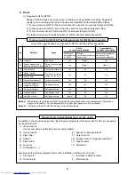
Страница 5: ...others do not mix in because pipes are affected by impurities such as water oxide scales oil etc Use the clean pipes Be sure to brazing with flowing nitrogen gas Never use gas other than nitrogen gas 4 For the earth protection use a vacuum pump for air purge 5 R410A refrigerant is azeotropic mixture type refrigerant Therefore use liquid type to charge the refrigerant If using gas for charging comp...

Страница 6: ...sulation resistance tester 4 Electroscope Note 1 When flaring is carried out for R410A using the conventional flare tools adjustment of projection margin is necessary For this adjustment a copper pipe gauge etc are necessary Note 2 Charging cylinder for R410A is being currently developed General tools Conventional tools can be used In addition to the above exclusive tools the following equipments ...

Страница 7: ...e gauge Gauge manifold Brazed Service port Service port Ø6 4 Copper pipe Ø6 4 Copper pipe Fully tightened Reducing valve Nitrogen gas Valve fully closed liquid side Connected to other terminal units Charge the refrigerant as below Recover the refrigerant and check there is no refrigerant in the equipment Leave it as it is for 1 to 2 minutes and check the indicator of the compound gauge does not re...

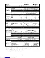
Страница 8: ... AP0092H MMU AP0122H 2 8 3 6 3 2 4 0 1phase 50Hz 230V 220V 240V 1phase 60Hz 220V Separate power supply for indoor units is required 0 23 0 24 0 23 0 24 0 021 0 021 0 021 0 021 0 30 0 30 0 30 0 30 Heat insulating material attached Zinc hot dipping steel plate 256 256 840 840 840 840 18 18 Finned tube Non flammable insulation Turbo fan 800 730 680 800 730 680 14 14 Standard filter Long life filter R...

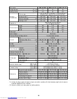
Страница 9: ...82H 4 5 5 6 5 0 6 3 1phase 50Hz 230V 220V 240V 1phase 60Hz 220V Separate power supply for indoor units is required 0 27 0 28 0 29 0 30 0 023 0 023 0 026 0 026 0 33 0 33 0 36 0 36 Heat insulating material attached Zinc hot dipping steel plate 256 256 840 840 840 840 20 20 Finned tube Non flammable insulation Turbo fan 930 830 790 1050 920 800 14 14 Standard filter Long life filter Remote controller...

Страница 10: ...eparate power supply for indoor units is required 0 38 0 39 0 38 0 39 0 43 0 45 0 036 0 036 0 036 0 036 0 043 0 043 0 42 0 42 0 42 0 42 0 59 0 59 Heat insulating material attached Zinc hot dipping steel plate 256 256 256 840 840 840 840 840 840 20 20 20 Finned tube Non flammable insulation Turbo fan 1290 920 800 1290 920 800 1320 1110 850 20 20 20 Standard filter Long life filter Remote controller...

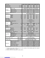
Страница 11: ...parate power supply for indoor units is required 0 73 0 76 0 88 0 92 0 88 0 92 0 088 0 088 0 112 0 112 0 112 0 112 0 87 0 87 1 23 1 23 1 26 1 26 Heat insulating material attached Zinc hot dipping steel plate 319 319 319 840 840 840 840 840 840 25 25 25 Finned tube Non flammable insulation Turbo fan 1970 1430 1070 2130 1430 1130 2130 1520 1230 68 72 72 Standard filter Long life filter Remote contro...

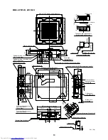
Страница 12: ...nnecting port Meterial PP For branch duct knockout square hole Ø150 For branch duct knockout square hole Ø150 2 positions For branch duct knockout square hole Ø150 Bottom face of ceiling An obstacle Standing 850 or less 300 or less Standing 661 or less The space that is necessary for equipping and service Drain upstanding size 1000 or more 1000 or more 15 or more 15 or more 1000 or more Bottom fac...

Страница 13: ...ut square hole Ø150 For branch duct knockout square hole Ø150 Ceiling panel sold separately Bottom face of ceiling 80 240 135 105 207 5 105 287 5 840 Unit external dimension 408 For branch duct knockout square hole Ø150 2 positions Electric parts box 77 129 10 5 74 Ø162 105 For branch duct knockout square hole Ø150 Drain pipe connecting port Meterial PP 112 44 172 Take in port of wiring Bottom fac...

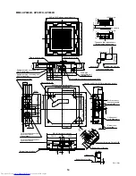
Страница 14: ...ockout square hole Ø150 For branch duct knockout square hole Ø150 Ceiling panel sold separately Bottom face of ceiling 80 240 135 105 207 5 105 287 5 840 Unit external dimension 408 For branch duct knockout square hole Ø150 2 positions Electric parts box 77 129 10 5 74 Ø162 105 For branch duct knockout square hole Ø150 Drain pipe connecting port Meterial PP 112 44 172 Take in port of wiring Bottom...

Страница 15: ...nnecting port Ø9 5 Liquid side Refrigerant pipe connecting port Ø15 9 Gas side For branch duct knockout square hole Ø150 2 positions An obstacle Standing 850 or less 300 or less Standing 661 or less The space that is necessary for equipping and service Drain upstanding size 1000 or more 1000 or more 15 or more 15 or more 1000 or more Bottom face of ceiling Indoor unit Unit mm Knockout for simple O...

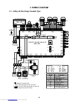
Страница 16: ... unit RED WHI Power supply single phase 220 240V 50Hz 220V 60Hz CN80 GRN 2 1 CN73 RED PNL EXCT OPTION FAN DRIVE GRL CN01 WHI 1 indicates the terminal block Letter at inside indicates the terminal number 2 A dotted line and broken line indicate the wiring site 3 indicates the control P C board CN02 BLU CN001 WHI Adapter for Wireless Remote controller Wired Remote controller BLK WHI WHI BLK CN03 RED...

Страница 17: ...AP0302H SWF 230 60 2R MP24ZN3N EDM MD12TF 3 EDM B25YGTF 3 EDM B40YGTF 2 Lead wire length 310 mm Vinyl tube Ø4 size lead wire length 1200 mm Vinyl tube Blue Ø6 size lead wire length 1000 mm Vinyl tube Black Ø6 size lead wire length 1000 mm Vinyl tube Red FS 0218 102 MDP 1401 Model Fan motor Motor for horizontal grille Pulse motor Pulse motor valve TA sensor TC1 sensor TC2 sensor TCJ sensor Float sw...

Страница 18: ... display Time of the timer with H mark is displayed When a trouble occurs the check code is displayed 5 Timer SET IN setup display When pushing the Timer SET IN button the display of the timer is selected in order of OFF OFF repeat OFF timer ON No display 6 Filter display If FILTER is displayed clean the air filter 7 TEST run display Displayed during a test run 8 Louver position display 4 way Air ...

Страница 19: ...ouver locked unit in the group including 1 indoor unit by 1 outdoor unit 19 Unit Number display Unit number of the indoor unit selected with the unit select button or abnormal indication of the indoor outdoor unit 20 Central control display Displayed when the air conditioner is used under the central control in combination with a central control remote controller In case the remote controller is d...

Страница 20: ...is off when stopped Also it flashes when operating the protection device or abnormal time 9 ON OFF button When the button is pushed the operation starts and it stops by pushing the button again When the operation has stopped the operation lamp and all the displays disappear 10 MODE button Operation mode select button Selects desired operation mode 11 UNIT LOUVER button Unit Louver select button Se...

Страница 21: ...lay changes in the order shown as follows DRY mode function is not provided to Concealed Duct High Static Pressure Type 3 Select air volume with FAN button One push of the button and the display changes in the order shown as follows When air volume is AUTO air volume differs according to the room temperature In DRY mode AUTO is displayed and the air volume is LOW In heating operation if the room t...

Страница 22: ...erature In case of cooling start the operation after approx 1 minute In case of heating the operation mode is selected in accordance with the room temperature and operation starts after approximately 3 to 5 minutes When you select the Auto mode it is unneces sary to set the fan speed The FAN speed display will show AUTO and the fan speed will be automatically controlled After the heating operation...

Страница 23: ...ting the louvers automatically direct downward While the air conditioner is in ready status for heating the louvers direct upward The swinging operation starts after heating ready status has been cleared but SWING is displayed on the remote controller even if the status is ready to heating u 4 way Air Discharge Cassette Type 2H series When the air conditioner is not operating the louvers automatic...

Страница 24: ...owever even if SWING FIX is pushed while the louver is swinging the louver position is displayed as follows and highest position of the louver may not be selected Display when swinging is stopped In this case push SWING FIX again two seconds later In COOL DRY operation the louver does not stop as it directs downward If stopping the louver as it directs downward during swing operation it stops afte...

Страница 25: ...ing operation SWING is displayed and the air direction automatically changes upward downward In case when one remote controller controls the multiple indoor units each indoor unit can be selected and its air direction can be set up 2 Push SWING FIX button again during swinging of the louver The air outlet louver can be stopped at the desired position 3 UNIT LOUVER To set up the air direction indiv...

Страница 26: ...very push of button the set time decreases in the unit of 0 5 hr 30 minutes 0 5 to 23 5 hours or 1 hr 24 to 168 hours Example of remote controller display In the case of 23 5 hours 1 In the case of 34 hours 2 shows 1 day 24 hours shows 10 hours Total 34 hours 3 Push SET button SETTING display disappears and timer time display goes on and or display flashes When ON timer is activated timer time ON ...

Страница 27: ...place where a great deal of machine oil is used Do not install the air conditioner in a place where it is usually exposed to strong wind such as in seaside area Do not install the air conditioner in a place where sulfureous gas generated such as in a spa Do not install the air conditioner in a vessel or mobile crane Do not install the air conditioner in an acidic or alkaline atmosphere in a hot sp...

Страница 28: ... cloth slightly dampened with lukewarm under 40 C water Cleaning of remote controller Use a dry cloth to wipe the remote controller A cloth dampened with cold water may be used on the indoor unit if it is very dirty Never use a damp cloth on the remote controller Do not use a chemically treated duster for wiping or leave such materials on the unit for long It may damage or fade the surface of the ...

Страница 29: ... Dust dirt clogging scratches Sound Dust dirt breakage Vibration balance Dust dirt appearance Dust dirt scratches Dust dirt clogging drain contamination Dust dirt scratches Maintenance Wash the heat exchanger when it is clogged Take appropriate measures when abnormal sound is generated Wash the filter with water when it is contaminated Replace it when it is damaged Replace the fan when vibration o...

Страница 30: ... strong wind blows continuously against the air outlet of the outdoor unit Heating operation When dust or dirt is excessively adhered to air filter of the indoor unit When the air outlet of the indoor unit is blocked Cooling heating operation of Modular Multi system air conditioner In Modular Multi system air conditioner each indoor unit can be individually controlled However cooling operation and...

Страница 31: ...prevent discharge of hot air Since refrigerant is flowed temporarily to prevent stay of oil or refrigerant in the stand by indoor unit sound of flowing refrigerant Kyururu or Shaa may be heard or white steam when other indoor unit operates in HEAT mode and cold air in COOL mode may be blow out Sound is generated when the expansion valve operates when power has been turned on Intermittent operation...

Страница 32: ...yed the mode enters in the trouble history mode 01 Order of trouble history is displayed in CODE No window Check code is displayed Indoor unit address in which an error occurred is displayed in UNIT No Every pushing of button used to set temperature the trouble history stored in memory is displayed in order The numbers in CODE No indicate CODE No 01 latest 04 oldest CAUTION Do not push CL button b...

Страница 33: ...tingly causes pipe burst and injuries on persons Perform installation work properly according to the Installation Manual Inappropriate installation may result in water leakage electric shock or fire When the air conditioner is installed in a small room provide appropriate measures to ensure that the concentration of refrigerant leakage occur in the room does not exceed the critical level Install t...

Страница 34: ... leaks and stays around the unit a fire may occur Upon approval of the customer install the air conditioner in a place that satisfies the following conditions Place where the unit can be installed horizontally Place where a sufficient servicing space can be ensured for safety maintenance and check Place where drained water will not cause any problem Avoid installing in the following places Place e...

Страница 35: ...blows directly if the ceiling height is lower than the standard Therefore change the setting switch according to height of the ceiling When using the high ceiling 1 or 3 with 4 way discharge system the draft is apt to be felt due to drop of the discharge temperature AP0092H Type and AP0122H Type air conditioners cannot be installed on a high ceiling u Height list of ceiling possible to be installe...

Страница 36: ...ur constructor or interior finish contractor In the process after the ceiling board has been removed it is important to reinforce ceiling founda tion frame and to keep horizontal level of installed ceiling correctly in order to prevent vibration of ceiling board 1 Cut and remove the ceiling foundation 2 Reinforce the cut surface of ceiling foundation and add ceiling foundation for fixing the end o...

Страница 37: ...ter leakage n Installation of remote controller Sold separately For installation of the wired remote controller follow the Installation Manual attached with the remote controller Pull out the remote controller cord together with the refrigerant pipe or drain pipe Be sure to pass the remote controller cord through upper side of the refrigerant pipe and drain pipe Do not leave the remote controller ...

Страница 38: ...f the ceiling Take the drain pipe out of the drain pipe joint with the indoor unit in 300 mm or less and bend up the pipe vertically Immediately after the pipe is bent up vertically lay the pipe making a down gradient Set downward grading immediately after raising up vertically n Check the draining In the test run check that water drain is properly performed and water does not leak from the connec...

Страница 39: ...e gas leakage Connected points n Pipe size n Permissible Piping Length and Height Difference They vary according to the outdoor unit For details refer to the Installation Manual attached to the outdoor unit Flaring Cut the pipe with a pipe cutter Remove burrs completely Remaining burrs may cause gas leakage Insert a flare nut into the pipe and flare the pipe As the flaring sizes of R410A differ fr...

Страница 40: ...arried out it will cause an electrical fire or smoke Be sure to install an earth leakage breaker that is not tripped by shock waves If an earth leakage breaker is not installed an electric shock may be caused Be sure to use the cord clamps attached to the product Do not damage or scratch the conductive core and inner insulator of power and inter connecting wires when peeling them Use the power cor...

Страница 41: ...ntroller Do not connect the high voltage circuit Make a loop on the wire for margin of the length so that the electric parts box can be taken out during servicing 1 Remove the cover of the electric parts box by taking off the mounting screws 2 positions and pushing the hooking section The cover of the electric parts box remains hanged to the hinge 2 Connect the power supply wire and remote control...

Страница 42: ...e U1 U2 U1 U2 U3 U4 L1 L2 L3 N U5 U6 L N A B A B U1 U2 U3 U4 L1 L2 L3 N U5 U6 U1 U2 L N A B A B U1 U2 L N A B A B U1 U2 L N A B Pull box Pull box Pull box Remote controller Remote controller Remote controller Outdoor Power supply 380V 415V 50Hz 380V 60Hz Outdoor Power supply 380V 415V 50Hz 380V 60Hz Earth leakage breaker Earth leakage breaker Header outdoor unit Indoor unit Indoor power supply 220...

Страница 43: ...llowing is the header unit Procedure 2 Each time you push UNIT LOUVER button indoor unit numbers in the control group change cyclically Select the indoor unit you want to change settings for The fan of the selected unit runs and the louvers start swinging You can confirm the indoor unit for which you want to change settings Procedure 3 Using TEMP buttons specify CODE No Procedure 4 Using timer TIM...

Страница 44: ...at least four seconds when the air conditioner is not working SETTING flashes Indicates CODE No 01 2 Select an indoor unit to be set by pushing UNIT LOUVER button left side of the button Indoor unit number changes each time you push the button 5 Push SET button to check the setting The display state changes from flashing to lighting and the setting is fixed 6 Push TEST button to end the setting Wh...

Страница 45: ...or unit senses room temperature usually Set the remote controller sensor to sense the temperature around the remote controller Select items following the basic operation procedure 1 2 3 4 5 6 Specify 32 for the CODE NO in Procedure 3 Select the following data for the SET DATA in Procedure 4 When the setting is canceled goes out Other operations are the same as those in How to set up louver lock No...

Страница 46: ...e 3 Procedure 1 Keep TEST button pushed for 4 seconds or more TEST is displayed on the display part and the selection of mode in the test mode is permitted Procedure 2 Push ON OFF button Procedure 3 Using MODE button select the operation mode COOL or HEAT Do not run the air conditioner in a mode other than COOL or HEAT The temperature controlling function does not work during test run The detectio...

Страница 47: ... downward 2 Cleaning with water If the dirt is terrible clean the louver by tepid water with neutral detergent or water Be careful to the direction of the louver when mounting Mount the louver so that the side with the mark faces upward and the arrow direction of the mark directs REQUIREMENT Be sure to clean the heat exchanger with pressurized water If a commercially available detergent strong alk...

Страница 48: ...g the operation If the display disappears operate the air conditioner according to the following Confirmation of error history for confirmation n Confirmation of error history When a trouble occurred on the air conditioner the trouble history can be confirmed with the following procedure The trouble history is stored in memory up to 4 troubles The history can be confirmed from both operat ing stat...

Страница 49: ...ror Other line connected during automatic address Sending error in communication between outdoor units Duplicated follower outdoor addresses Decrease of No of connected outdoor units Follower outdoor unit error IPDU communication error Judging device Remote controller Remote controller Indoor Indoor I F I F Indoor I F Remote controller Indoor I F I F I F Indoor I F I F I F I F I F I F I F Check co...

Страница 50: ...n Phase missing detection Phase error Heat sink overheat error Indoor overflow error Indoor fan motor error Outdoor liquid back detection error Gas leak detection Discharge temp TD2 error 4 way valve inverse error High pressure protective operation Outdoor fan IPDU error G TR short protection error Comp position detective circuit system error Other indoor unit error Group terminal unit error Error...

Страница 51: ... outline Connector CN082 6P Blue 1 Controls super heat in cooling operation 2 Controls under cool in heating operation 3 Recovers refrigerant oil in cooling operation 4 Recovers refrigerant oil in heating operation Connector CN104 2P Yellow 1 Detects indoor suction temperature Connector CN100 3P Brown 1 Controls PMV super heat in cooling operation Connector CN101 2P Black 1 Controls PMV under cool...

Страница 52: ... FAN COOL DRY HEAT AUTO SHRM only Control outline Air conditioner stops Fan operation Cooling operation Dry operation Heating operation Ta and Ts automatically select COOL HEAT operation mode for operation The operation is performed as shown in the following figure according to Ta value at the first time only In the range of Ts 1 Ta Ts 1 Cooling thermo OFF Fan Setup air volume operation continues ...

Страница 53: ...ied out as shown below When 1 5 exceeds against Tsh 10 minutes and after thermo OFF heating operation Thermo OFF exchanges to cooling operation Description in the parentheses shows an example of cooling ON OFF When 1 5 lowers against Tsc 10 minutes and after thermo OFF cooling operation Thermo OFF exchanges to heating operation 2 For the automatic capacity control after judgment of cooling heating...

Страница 54: ...e HEAT Value in the parentheses indicates one when thermostat of the remote controller works Value without parentheses indicates one when thermo stat of the body works If the air speed has been changed once it is not changed for 1 minute However when the air speed exchanged the air speed changes When heating operation has started select an upward slope for the air speed that is the high position I...

Страница 55: ... the operation shifts to C zone In defrost time the control point is set to 6 C TCJ Temperature of indoor heat exchanger sensor In D and E zones priority is given to remote control ler air speed setup In A zone is displayed 7 Prevention of cold air discharge E B A A zone OFF B zone Over 26 C below 28 C ULTRA LOW LL C zone Over 28 C below 30 C LOW L D zone Over 30 C below 32 C MED H E zone HIGH HH ...

Страница 56: ...ted for 45 minutes the thermostat is forcedly off In N zone the timer count is interrupted and held When shifting to M zone again the timer count restarts and continues If L zone is detected the timer is cleared and the operation returns to normal operation Reset conditions 1 TC1 12 C and TC2 12 C and TCJ 12 C 2 20 minutes passed after stop P1 Q1 C a K J I P2 Q2 C L N M value When the power supply...

Страница 57: ...drain pump 2 During operation of the drain pump if the float switch operates the drain pump continuously operates and a check code is issued 3 During stop status of the drain pump if the float switch operates the thermostat is forcedly off and this control operates the drain pump After continuous operation of the float switch for approx 5 minutes this control stops the operation and a check code i...

Страница 58: ...type remote controller In case of AI NET central control Operation possible Operation impossible In case of TCC LINK central control HEAT READY display In case of wired remote controller type Central control display Goes on in the central control mode Display flashes when an item of the operation prohibited was changed on the remote controller In case of wireless remote controller type the display...

Страница 59: ...ked louver closes fully when the unit stops and the louver is automatically set to horizontal discharge position when PRE HEAT Heating ready is displayed heating thermo is off Individual air direction setup Pushing UNIT LOUVER Louver select button enables every discharge port to set up the air direction The louver numbers that are displayed on the display part correspond to those in the following ...

Страница 60: ...button was pushed to select SWING No display for the standard swing Remarks On the remote controller before the wired remote controller RBC AMT32E the mode cannot be moved to the select mode even if pushing SWING FIX button for a long time Carry out setting operation during stop of the unit otherwise the unit stops operation The standard swing performs the same swing operation as the present opera...

Страница 61: ...discharge position Horizontal discharge position Horizontal discharge position Horizontal discharge position Full close position It is position check operation and it does not link with the real louver and air direction setup Illustration on the remote controller screen 19 DC motor 1 When the fan stator positioning is performed for the starter and the rotor Vibrate slightly 2 DC motor operates acc...

Страница 62: ...ion Network adaptor Option Indoor unit 1 Network adaptor P C board MCC 1401 DC5V PMV Louver motor Indoor fan motor CPU DC5V DC5V 3 CN2 CN1 Wired remote controller Up to 2 units Schedule timer in weekly timer mode Weekly timer Function setup LCD driver CPU Power circuit Power circuit Power circuit Transformer Switch setup EEPROM TA sensor TC1 sensor TC2 sensor TCJ sensor Float input HA Outdoor unit...

Страница 63: ...V DC20V DC5V Power circuit Outside output Fan motor control circuit Start Alarm Ready Thermostat ON COOL HEAT FAN Emergent operation SW Function setup SW Display LED MCU AC synchronous signal input circuit BUS communication circuit MCU EEPROM TA sensor TC1 sensor TC2 sensor TCJ sensor Float input HA Driver Buzzer Remote controller communication circuit Remote controller communication circuit CPU D...

Страница 64: ...rm Ready Thermostat ON COOL HEAT FAN Emergent operation SW Function setup SW Display LED MCU AC synchronous signal input circuit BUS communication circuit MCU EEPROM TA sensor TC1 sensor TC2 sensor TCJ sensor Float input HA Driver Buzzer Remote controller communication circuit Remote controller communication circuit Remote controller communication circuit CPU DC 280V Network adaptor Option Indoor ...

Страница 65: ...oor central control communication LED D503 Yellow Output for FS unit CN81 Black DC12V PMV output CN82 Blue DC12V Power supply LED of microprocessor D501 Red Optional output CN60 White DC12V Power supply CN67 Black AC220 240 DC fan return CN334 White Power supply LED of remote controller D403 Red Louver CN510 White DC12V Optional power supply CN309 Yellow AC200V HA T10 CN61 Yellow DC12V Indoor Outd...

Страница 66: ...tatus 7 3 Functions at test run n Cooling Heating test run check The test run for cooling heating can be performed from either indoor remote controller or outdoor interface P C board 1 Start Finish operation of test run Test run from indoor remote controller Wired remote controller Refer to the below item of Test run of the wired remote controller Wireless remote controller Refer to the next page ...

Страница 67: ...ely Set 30 C using Temperature set button immediately after confirmation of the receiving sound Pi after confirmation of the receiving sound Pi Next carry out the procedures 3 4 3 4 After approx 10 seconds all the indication lamps on the receiving part of the wireless remote controller ON TIMER and Ready flash and start the operation Repeat operation of procedure 2 and after if the lamps do not fl...

Страница 68: ...g DISP pin CN72 on the indoor P C board in addition to short circuit of CHK pin CN71 on the indoor P C board the minimum opening degree 30pls can be set to the indoor PMV only When open DISP pin the maximum opening degree 1500pls can be obtained again How to clear Open CHK pin While the system is operating it stops once but automatically returns to operation after several minutes Fan motor Indoor ...

Страница 69: ...m remote controller DN 31 HA ON OFF input J01 YES NO Pulse At shipment Static input select Operation stop of main remote controller is permitted prohibited by input ON during operation Answerback of HA ON during alarm output ON when outdoor unit is defrosted ON during Real thermostat ON Compressor ON ON when operation mode is cooling system COOL DRY Cool Heat Auto cooling ON when operation mode is...

Страница 70: ...e group control are successively displayed In this time the fan of the selected indoor unit only is turned on 3 Specify the item code DN using the setup temperature and buttons 4 Select the setup data using the timer time and buttons When selecting the DN code to 33 change the temperature indication of the unit from C to F on the remote controller 5 Push SET button OK if display goes on To change ...

Страница 71: ...assette 0000 Unfixed 0001 to 0034 0001 No 1 unit to 0030 No 30 unit 0001 No 1 unit to 0064 No 64 unit 0000 Individual 0001 Header unit of group 0002 Follower unit of group 0000 No louver 0001 Swing only 0002 1 way Air Discharge Cassette type Under Ceiling type 0003 2 way Air Discharge Cassette type 0004 4 way Air Discharge Cassette type 0000 0 deg to 0010 10 deg For setup temperature reversal of C...

Страница 72: ... Standard 3 0m 3 3m 3 6m 3 0m 3 3m 3 6m At shipment 0001 High ceiling 3 3m 3 5m 3 8m 3 3m 3 5m 3 8m 0003 High ceiling 3 6m 3 8m 3 6m 3 8m 0000 Standard filter At shipment 0000 Available Operable 0001 Unavailable Operation prohibited At shipment 0000 Standard 0000 Available TYPE Item code 10 1 Initial setting value of EEPROM installed on the service P C board Indoor unit capacity Item code 11 Setup...

Страница 73: ...ion signal Output during normal operation 3 Error signal Output during alarm Serial communication error or indoor outdoor protective device operation 2 Wiring diagram using remote control interface TCB IFCB 4E2 Input IFCB 4E2 No voltage ON OFF serial signal Output No voltage contact for operation error display Contact capacity Below Max AC240V 0 5A 1 2 3 4 5 6 CN61 T10 YEL 1 2 3 4 1 2 3 4 5 6 CN13...

Страница 74: ...y In this time the fan of the selected indoor unit only turns on 3 Using the setup temp or button specify the item code 31 4 Using the timer time or button select the setup data At shipment The setup data are as follows Setup data Handling of operation of air to air heat exchanger or ventilating fan Unavailable At shipment Available 5 Push SET button OK if display goes on To change the selected in...

Страница 75: ...that card is taken out from the card switch box When the card switch box does not perform the above contact operation convert it using a relay with b contact 2 Operation Handle the wired remote controller switch in the following procedure Use the wired remote controller switch during stop of the system 1 Push concurrently SET CL TEST buttons for 4 seconds or more 2 Using the setup temp or button s...

Страница 76: ...oup control Outdoor Outdoor Indoor Indoor Indoor Indoor Indoor Master unit Sub unit Line address 1 Indoor unit address 1 Group address 1 1 2 2 1 3 2 2 1 2 2 2 2 Operation procedure 1 2 3 4 5 6 1 3 6 9 END 11 2 5 8 4 7 10 SET TIME TIMER SET TEST FILTER RESET TEMP CL FAN SAVE SWING FIX VENT MODE ON OFF UNIT LOUVER 7 8 9 10 11 END Note 1 When setting the line address from the remote controller do not...

Страница 77: ...emote controller Group control unit other unit numbers are also displayed every pushing UNIT LOUVER button 2 To know the position of indoor unit by address To confirm the unit No in the group control Follow to the procedure during operation in this procedure the indoor units in group control stop Procedure The indoor unit numbers in the group control are successively displayed and fan louver and d...

Страница 78: ...rol is displayed one after the other In this time fan and louver of the selected indoor unit only operate ò 3 Using the set temperature TEMP buttons specify the item code DN ò 4 Using the timer time TIME buttons select the set data ò 5 Push SET button OK if indication lights To change the selected indoor unit proceed to Procedure 2 To change item to be set up proceed to Procedure 3 ò 6 Pushing TES...

Страница 79: ...UNIT LOUVER SWING FIX button ò 3 Determine the selected line address using SET button The address of the indoor unit connected to the refrigerant piping of the selected outdoor unit is dis played and the fan and the louver are on ò 4 Every pushing UNIT LOUVER button the indoor unit No in the identical piping is displayed one after the other Only fan and louver of the selected indoor unit start ope...

Страница 80: ...address is not displayed ò 4 TIME button push up down the indoor address of the SET DATA The set data is changed to a new address ò 5 Push SET button to determine the set data ò 6 Every pushing UNIT LOUVER button the indoor unit No in the identical piping is displayed one after the other Only fan and louver of the selected indoor unit start operation Repeat the Procedures 4 to 6 to change all the ...

Страница 81: ... to service monitor mode 2 Push TEMP button to set the item code to FF 3 The display of A part in the following figure is counted as with 5 seconds interval When appear the error was cleared However counting from is repeated on the display screen 4 When pushing TEST button the status becomes normal How to clear error of indoor unit The error of indoor unit is cleared by ON OFF button of the remote...

Страница 82: ...y compressor 1 is ON 10 Only compressor 2 is ON 11 Both compressor 1 and 2 are ON Note 3 For the CODE No an example of header unit is described Note 4 Upper girder of CODE No indicates the outdoor unit No 1 Header unit A 2 Follower unit B 3 Follower unit C 4 Follower unit D CODE No 00 01 02 03 04 05 08 F2 F3 0A 0B 0C 0D Data name Room temp Under control Note 1 Room temp Remote controller Indoor su...

Страница 83: ... controller ON in hardware 3 D503 Yellow Indoor Outdoor central control D503 goes on for 5 seconds at the first half during communication with the central controller D503 flashes for 5 seconds with 0 2 second interval at the latter half during communication with outdoor unit Goes on for 0 1 second goes off for 0 1 second 4 D504 Green Remote controller communication D504 goes on for 5 seconds at th...

Страница 84: ...Indoor fan does not stop Start stop operation on remote controller is unavailable Check items Is not delayed for 3 minutes 3 minutes after compressor OFF Is not thermostat OFF Is not the fan operating or timer Is not the system initially communicating Heating operation cannot be performed under condition of outside temperature 21 C or higher Cooling operation cannot be performed under condition of...

Страница 85: ...ation error between indoor and outdoor Duplicated indoor address Communication error between indoor MCU Regular communication error between header and follower in indoor unit Indoor heat exchanger temp sensor TCJ error Indoor heat exchanger temp sensor TC2 error Indoor heat exchanger temp sensor TC1 error Room tem Sensor TA error Indoor or other P C board error Duplicated setting of header in indo...

Страница 86: ...etects error Check code display TCC LINK central C05 C06 C12 P30 AI NET central Network adapter use 98 97 99 23 b7 Outdoor 7 segment Auxiliary code Sensor lamp display Block display Operation Timer Ready Flash Is not displayed In shared use of remote controller According to unit with alarm Abovementioned Main defective position Central control system communication send error Central control system...

Страница 87: ...oor liquid temp sensor TL error Outdoor external temp sensor TO error Outdoor suction temp sensor TS1 error Outdoor temp sensor TE TL miswiring Outdoor pressure sensor Pd Ps miswiring Low pressure Ps sensor error High pressure Pd sensor error Outdoor EEPROM error Description When signal did not come from indoor unit Decrease of connected indoor units When signal could not send to indoor unit Statu...

Страница 88: ...D1 temp error Detection of open phase Negative phase error Heat sink overheat error There is outdoor unit with detection of overflow Outdoor liquid back detection error Gas leak detection Outdoor discharge TD2 temp error 4 way valve inverse error High pressure protective operation Description When case thermo of compressor 1 performed protective operation Protective detection operation by low pres...

Страница 89: ... side P29 01 Compressor 1 side 02 Compressor 2 sid TCC LINK central remote controller F13 H01 H02 H03 P04 P07 P22 P26 P29 AI NET central Network adapter use 43 1F 1d 17 21 1C 1A 14 16 Sensor lamp display Block display Operation Timer Ready Flash A l l l l l l l A l A l A l A l A Main defective position Outdoor IGBT incorporated temp sensor TH error Compressor break down Compressor error Lock Curre...

Страница 90: ... code Indoor unit No in which an error occurred 3 2 1 SET TIME TIMER SET TEST FILTER LTER L RESET TEMP CL FAN SAVE AVE A SWING FIX VENT MODE ON OFF UNIT LOUVER T Procedure 1 2 3 Description When pushing SET and TEST buttons simultaneously for 4 seconds or more the below display appears If Service Check is displayed the mode enters in the error history mode 01 Error history order is displayed in CO...

Страница 91: ...stop 1 Push and SET buttons in succession for 4 seconds or more 2 SERVICE CHECK goes on and Item code 01 goes on 3 When selecting flash the group number if there is the alarm history the UNIT number and the latest alarm history are displayed alternately In this time the temperature cannot be set up 4 To confirm the alarm history other than the latest one push temp set to select Item code 01 to 04 ...

Страница 92: ...r between indoor unit and outdoor unit Communication interruption between indoor and outdoor units Communication receiving error between indoor and outdoor units decrease of No of connected indoor units Communication sending error between indoor and outdoor units No indoor unit during setting of automatic address No of connected indoor units capacity over Error of No of center unit Disagreement of...

Страница 93: ...pressure sensor Ps Misconnection of pressure sensor in outdoor unit Low pressure sensor Ps error Pressure sensor error in outdoor unit High pressure sensor Pd error Indoor unit EEPROM error Compressor break down Compressor lock Outdoor unit compressor system error Current detection circuit error Compressor 1 case thermo operation Low pressure Ps drop error Protections stop of outdoor unit Oil face...

Страница 94: ...mer Ready Simultaneous flash Operation Timer Ready Alternate flash Check code Cause of trouble occurrence During test run COOL HEAT disagreement Automatic cooling heating setup to automatic cooling heating unavailable model heating setup to cooling only model ...

Страница 95: ...eriod from the indoor unit which has been used to send signals Transmission from outdoor to indoor cannot continue for 30 seconds Multiple indoor unit address setup are duplicated In 2 remote controller control including wireless both are setup as master Header indoor unit stops and other indoor unit is operating Communication was not succeeded after power was supplied or during communication When...

Страница 96: ...ated The signal was not returned for constant from the outdoor unit which was receiving signal Outdoor header unit received error code from outdoor follower unit Check item position Check the communication line connection between indoor and outdoor Check the electric power line error in indoor Check the noise of surrounding devices Power failure Check indoor P C board error Check the connection ca...

Страница 97: ...zero Open Short Resistance value of sensor is infinite or zero Open Short Resistance value of sensor is infinite or zero Open Short Resistance value of sensor is infinite or zero Open Short Check item position Check connection of communication connector and disconnection between IPDU and I F P C board Check outdoor P C board I F IPDU Fan IPDU error Check external noise Check connection cabling of ...

Страница 98: ...hile header compressor stopped current flowed more than the specified current and was detected Check item position Check installation of TE1 sensor and TL sensor Check characteristics of TE1 and TL sensor resistance value Check outdoor P C board I F error Check connection of high pressure Pd sensor connector Check connection of low pressure Ps sensor connector Check pressure sensors Pd and Ps erro...

Страница 99: ... 4 way valve error Check refrigerant shortage Check full opening of service valve Discharge gas suction gas and liquid side Check outdoor PMV clogging PMV1 2 Check SV2 circuit and SV4 circuit error Check low pressure Ps sensor error Check indoor air filter clogging Check valve open of indoor PMV Check refrigerant pipe clogging Check outdoor fan operation All heating mainly heating part cooling ope...

Страница 100: ...MV clogging PMV1 2 Check SV42 valve leak Check miscabling misinstallation of SV41 and SV42 Check valve opening of indoor PMV Check 4 way valve error Check refrigerant shortage Check TK1 sensor coming off Check characteristics of TK1 sensor resistance value Check TK1 TK2 TK3 and TK4 misconnection Check operation error of SV3E valve Check capillary clogging of oil equation circuit and operation erro...

Страница 101: ...ress was not yet set up Indoor unit capacity was unset On the I F P C board for service jumper line was not cut according to the model When outdoor unit models are intermingled When 1 2 series of SHRM was intermingled An indoor unit which is not connected with FS unit is driving without setup for cooling only mode Duplicated central control addresses There were more than four outdoor units No of I...

Страница 102: ... PMV PMV1 2 Check characteristics of TD1 sensor resistance value Check refrigerant shortage Check 4 way valve error Check leakage of SV4 circuit Check SV4 circuit Miswiring and misinstallation of SV41 and SV42 Check connection of high pressure SW connector Check Pd pressure sensor error Check full opening of outdoor service valves Gas side Liquid side Check outdoor fan error Check outdoor fan moto...

Страница 103: ... clogging of balance pipe Check clogging of SV3B circuit Check outdoor P C board I F error Check capillary clogging of oil return circuit from oil separator Check leakage of stop valve in discharge assembly part Check refrigerant shortage Check full open of outdoor service valves gas side liquid side Check outdoor PMV clogging PMV1 2 Check characteristics of TS1 sensor resistance value Check 4 way...

Страница 104: ...ary code 04 External cause such as blast When difference between target rpm and real rpm is 25 or more Restart after 6 seconds Auxiliary code 0D Fan IPDU position detection circuit Position detection was not normally performed Windless status Auxiliary code 0C External cause such as blast Position detection was not normally performed Windy status Restart after 6 seconds Instantaneous over current ...

Страница 105: ...tinued Operation continued Error detection condition Signal is not transmit from central control device Signal is not received from central control device Error was input in general purpose equipment control interface An error occurred in follower unit of the group control P30 is displayed only on the central remote controller Central control addresses were duplicated Check item position Check cen...

Страница 106: ...ics 0 10 20 10 20 30 40 50 Characteristic 1 Temperature C Indoor TA sensor Resistance k W 50 0 100 150 200 5 0 10 15 20 20 30 10 0 10 20 30 40 50 60 70 80 90 100 Characteristic 2 Temperature C Indoor TC1 TC2 TCJ sensors Resistance k W 10 C or lower Resistance k W 10 C or higher ...

Страница 107: ...and then slide it to the arrow direction in order to open the claws and the electric parts box cover 2 Attachment 1 Close the electric parts cover and slide it hook claw of the electric parts box claw of the electric parts box cover and the Dharma doll hole and then insert pin of the bell mouth into hole of the electric parts box cover 2 Tighten the fixing screws A and B and then fix the electric ...

Страница 108: ...e the cap of the knob side at first 2 Attachment 1 Hook strap of the adjust corner cap securely to pin of the ceiling panel 2 Insert claw of the adjust corner cap into the square hole of the panel 2 positions 3 Push claws of the adjust corner cap into the positions indicated with arrow marks so that they fit in 3 positions Adjust corner cap 3 Push into positions with arrow marks Adjust corner cap ...

Страница 109: ...the panel fixing bracket and then slide the panel fixing bracket inward 3 Tighten in the panel fixing screw to fix the ceiling panel 4 Following to work of item 2 of 3 attach the adjust corner cap as before 5 Connect the louver connector CN510 White 20P as before and then fix the lead wire with clamp 6 Following to work of item 2 of 2 mount the electric parts box cover and the suction grille as be...

Страница 110: ...detection 3P White CN82 PMV 6P Blue NOTE Unlock the lock of the housing part and then remove the connector 3 Unlock the locks of the card edge spacer 6 positions and then remove the control P C board 2 Attachment 1 Fix the control P C board to the card edge spacer 6 positions 2 Connect the connector removed in item 1 as before and then fix the wiring with the clamp 3 Following to work of item 2 of...

Страница 111: ...pe etc 4 Turn the drain cap once again to OPEN direction to remove it 2 Attachment 1 Insert the drain cap inside turn it to CLOSE direction until the position where Clashed sound is heard and it cannot be turned more over Position where mark of the drain pan matches with mark of the drain cap inside and then fix it NOTE When attaching the drain cap inside remove dirt attached to the packing And ti...

Страница 112: ...emove the bell mouth Ø4 10 8 pcs 6 Remove the fixing screws and then remove the nut cap Ø4 10 2 pcs 7 Remove the fixing nut and then remove the turbo fan M8 nut with flange 1 pc 8 Remove the fixing screws and then remove the motor lead holding bracket Ø4 8 2 pcs 9 Cut the bundling band and then remove it from the clamp 10 Remove the fixing nut and then remove the fan motor Ø6 nut 3 pcs 2 Attachmen...

Страница 113: ...clamp 5 Following to work of item 2 of 2 mount the electric parts box cover and the suction grille as before XCAUTIONX When exchanging the fan motors of the models MMU AP0092H to AP0320H take off lead wire from the clamp filter which is connected to CN334 of the fan motor to be exchanged and then connect the removed lead wire to a new fan motor Remarks Clamp Fan motor lead M6 nut Fan motor an moto...

Страница 114: ...e connector of the drain pump lead wire through the wiring taking out port 2 Connect the drain hose to the drain pump as before NOTE Insert the drain hose up to the end of the drain pump connecting part apply band to the white mark position of the hose and then set the band knob upward 3 Return the drain pump to the indoor unit and then mount it as before using the fixing screws Ø4 10 3 pcs 4 Conn...

Страница 115: ...e float switch assembly Ø4 25 1 pc 2 Attachment 1 Mount the float switch assembly as before with the fixing screw NOTE When mounting match hole of the float switch assembly with projection of the drain pan 2 Mount the bell mouth as before Ø4 10 8 pcs 3 Following to works of item 2 of 7 and works from 2 to 5 attach the parts as before Remarks 10 Drain pan 1 Detachment 1 Carry out works of item 1 of...

Страница 116: ... butyl rubber adhered to the main unit of the pulse motor valve PMV until PMV can be seen and then loosen the nuts fixing PMV motor with double spanner to remove PMV motor 2 Attachment 1 Mount PMV motor and relay connector as before NOTE Control the tightening torque for the PMV body and PMV motor to 7 84 0 98Nm Remarks PMV motor PMV body ...

Страница 117: ... 4 Remove the fixing screws and then remove the piping cover Ø4 10 3 pcs 5 Remove the drain hose from the drain pump and remove the fixing screws to remove the drain pump stand Ø4 8 3 pcs 6 While pushing the heat exchanger remove the fixing band fixing screws and the heat exchanger Ø4 8 3 pcs 2 Attachment 1 Mount the heat exchanger with the fixing band and the fixing screws Ø4 8 3 pcs 2 Fix the pa...

Страница 118: ...gs and perform the cooling cycle confirmation through the trial operation Replacement procedures Case 1 Before replacement the indoor unit can be turned on and the setting data can be read out by wired remote controller operation EEPROM data read out 1 Refer to page 119 ò Replacement of P C board for indoor unit servicing and power on 2 Refer to page 119 ò Writing the read out EEPROM data 3 Refer ...

Страница 119: ...acement procedures Step 1 Replace the P C board for indoor unit servicing At this time perform the same setting of the jumper wire J01 setting cut switch SW501 short circuit connector CN34 as the setting of the P C board before replacement Step 2 It is necessary to set indoor unit to be exchanged Remote controller 1 1 Based upon the system configuration turn on power of the indoor unit with one of...

Страница 120: ... temperature setting 3 5 Select the capacity by pushing buttons for the timer setting 4 For example 027 Type is set to 0012 Refer to Item code 11 on page 6 6 Push SET button The setting completes if the setting data are displayed 5 Setting 4 way Air Discharge Cassette indoor unit model only 7 Using the set temperature buttons set to the CODE No DN 8 Using the timer time buttons set the dat 0001 9 ...

Страница 121: ... status 6 In a group operation turn off the power supply once return the group wires between indoor units and CN41 connectors as before and then turn on power of all the indoor unit It takes approx 1 min until the remote controller operation is available again The CODE No DN are ranged from to The CODE No DN is not limited to be serial No Even after modifying the data wrongly and pushing SET butto...

Страница 122: ...ring installation type 0 0001 No auto mode Automatically selection by cooling heating 0000 Heat pump connected outdoor unit Depending on model type Depending on capacity type 0099 Not determined 0099 Not determined 0099 Not determined Depending on Type 0003 3 deg Ts 1 5 0000 None 0002 Humidifier 0000 Not available 0000 Body sensor 0000 Standard 0000 Available 0001 Standard 0000 Not fixed 0000 Not ...

Страница 123: ...AP0182H AP0242H 261 202 249 242 244 223 210 211 206 207 245 259 262 243 221 260 205 246 264 263 215 209 228 251 254 203 204 218 217 250 216 230 231 232 233 252 253 227 228 229 251 254 255 263 247 257 220 241 236 258 213 234 248 240 256 219 222 226 224 225 227 229 255 ...

Страница 124: ...36 43197197 Screw Fix Panel 240 4312C039 Motor Fan 241 43119497 Cover Ass y 242 43139166 Cap Nut 243 43179147 Gasket 244 43177010 Pump Ass y MDP 1401 245 43151299 Switch Ass y Float FS 0218 102 246 43179145 Lid Ass y Outside 247 43170254 Socket Ass y Drain 248 43197155 Washer 249 43097212 Nut 250 43107215 Holder Sensor 251 43047609 Bonnet 252 43147195 Bonnet 1 2 IN 253 43194029 Bonnet 254 43149355...

Страница 125: ...3050425 Sensor Ass y Service TC F6 402 43050426 Sensor Service TA 403 43150320 Sensor Ass y Service TG F4 404 43160574 Terminal 4P 405 43160575 Terminal Block 2P 20A 406 4316V379 P C Board Ass y MCC 1570 Model Name MMU AP 0092H 0122H 0152H 0182H 0242H 2 2 2 2 2 1 1 1 1 1 1 1 1 1 1 1 1 1 1 1 1 1 1 1 1 1 1 1 1 1 ...

Страница 126: ...44 223 212 245 235 206 208 205 260 246 222 226 224 225 259 262 243 221 202 211 234 248 240 217 219 203 204 218 256 250 263 247 257 220 239 213 258 241 236 214 216 228 251 254 231 233 253 MMU AP0272H AP0302H AP0362H AP0482H AP0562H ...

Страница 127: ...shion 238 43197199 Washer 239 4312C038 Motor Fan 240 4312C039 Motor Fan 241 43119497 Cover Ass y 242 43139166 Cap Nut 243 43179147 Gasket 244 43177010 Pump Ass y MDP 1401 245 43151299 Switch Ass y Float FS 0218 102 246 43179145 Lid Ass y Outside 247 43170254 Socket Ass y Drain 248 43197155 Washer 249 43097212 Nut 250 43107215 Holder Sensor 251 42047609 Bonnet 253 43194029 Bonnet 254 43149355 Nut F...

Страница 128: ...3050425 Sensor Ass y Service TC F6 402 43050426 Sensor Service TA 403 43150320 Sensor Ass y Service TG F4 404 43160574 Terminal 4P 405 43160575 Terminal Block 2P 20A 406 4316V379 P C Board Ass y MCC 1570 Model Name MMU AP 0272H 0302H 0362H 0482H 0562H 2 2 2 2 2 1 1 1 1 1 1 1 1 1 1 1 1 1 1 1 1 1 1 1 1 1 1 1 1 1 ...

Страница 129: ...x Panel 313 43407149 Plate Fix Panel 314 43407150 Hook ABS 315 43407154 Cap AXIS POM 316 43403010 Cover Ass y Motor 317 43403011 Cover Ass y 318 43403012 Cover Ass y 319 43407155 Fix Motor ABS 320 43407156 Fix Motor ABS 321 43460125 Lead Motor 322 43400077 Panel Front PS W 323 43109423 Louver ABS 324 43109424 Louver ABS Model Name RBC U31 U31PG W E U31PG WS E U31PGS W E U31PGS WS E 1 1 1 1 1 1 1 1...

Страница 130: ... Ass y Remote Receiver 354 43462010 Cover WRS ABS 355 43461006 Sheet PC 356 43108018 Cover Panel WRS 357 43108019 Cover Panel WRS 358 43460126 Lead Model Name RBC AX31U W E RBC AX31U WS E 1 1 1 1 1 1 1 1 1 1 RBC AX31U W E RBC AX31U WS E 354 358 353 355 356 357 ...

Страница 131: ...TOSHIBA CARRIER CORPORATION 23 17 TAKANAWA 3 CHOME MINATOKU TOKYO 108 8580 JAPAN Copyright 1999 to 2008 TOSHIBA CARRIER CORPORATION ALL Rights Reserved ...

Отзывы: