


– 97 –
No. Part name
Procedure
Remarks
l
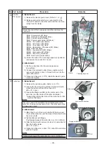
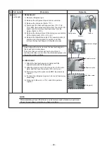
Fan motor
1. Detachment
1) Remove the turbo fan, electric parts cover, wiring cover
and wiring fixing plate.
(Refer to
h
-1,
d
-1,
i
-1-2,
i
-1-3.)
2) Remove the fan motor connector (CN210, White, 7P)
connected to the control P.C. board, and then take off
the lead wires from the clamp.
3) Remove the shoulder screws (Black, 2pcs.) of the
motor lead wiring cover, and separate the lead wires
and the lead wire cover.
4) Remove the hexagon nuts (M6) which fix the motor,
and the washers. (3 pcs. Each).
* When taking off them, hold them with a hand so that
motor will not fall down.
5) Remove the motor with rubber cushion from the bolt.
2. Attachment
1) Pass rubber cushion of the motor in the bolt, put the
washer and the hexagon nut in this order, and then
tighten to fix them.
(Tightening toque: 4.9 ± 0.5N•m)
2) Pass the lead wire through the motor lead wire fixing
plate removed in 1-3), and then fix it with shoulder
screw.
3) Perform wiring of the motor lead wires as original,
connect the connector to the control P.C. board, and
then attach the wiring fixing plate and the wiring cover.
4) Following to works in
h
-2 and
d
-2, attach the turbo
fan and the electric parts covers.
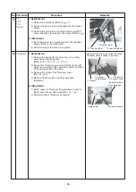
PMV motor
1. Detachment
1) Remove the drain pan. (Refer to
i
-1)
2) Remove the PMV connectors (CN82, Blue, 6pcs.)
connected to the control P.C. board, and take off the
lead wires from the clamp.
3) Using a cutter, etc., enter a break on the butyl rubber
adhered on PMV body, peel the rubber until PMV body
can be visible. (Adhere it as original after exchange.)
* Peel butyl rubber so that the main body will not be
damaged.
4) After loosening the nut which fixes PMV motor with the
two spanners, remove the PMV motor.
2. Attachment
1) Attach the PMV motor as original.
NOTE
Tightening torque of the PMV body and the PMV motor:
7.84 ± 0.98N•m.
S
ho
u
lder
s
crew
s
(Bl
a
ck)
Motor le
a
d wire cover
Bolt
Hex
a
gon n
u
t
W
as
her
R
ubb
er
c
us
hion
PMV
b
ody
PMV motor
N
u
t
Tighten the n
u
t of PMV motor.


