


– 2 –
CONTENTS
PRECAUTIONS FOR SAFETY .................................................................................... 6
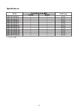
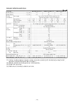
1. SPECIFICATIONS .................................................................................................. 13
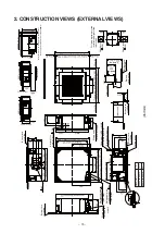
2. CONSTRUCTION VIEWS (EXTERNAL VIEWS) .................................................... 15
3. WIRING DIAGRAMS .............................................................................................. 16
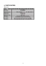
4. PARTS RATING ...................................................................................................... 17
5. REFRIGERANT CYCLE DIAGRAM ....................................................................... 18
6. CONTROL OUTLINE.............................................................................................. 19
7. APPLIED CONTROL AND FUNCTIONS
(INCLUDING CIRCUIT CONFIGURATION) ........................................................... 30
7-1. Indoor controller block diagram ....................................................................................... 30
7-1-1. In Case of Connection of Wired (Simple) Remote Controller .............................. 30
7-1-2. In Case of Connection of Wireless Remote Controller ........................................ 31
7-1-3. Connection of Both Wired (Simple) Remote Controller and Wireless Remote
Controller .................................................................................................................. 32
7-2. Indoor Print Circuit Board ................................................................................................. 33
7-3. Optional connector specifications of indoor P.C. board ............................................... 34
7-4. Test operation of indoor unit ............................................................................................ 35
7-5. Method to set indoor unit function DN code................................................................... 38
7-6. Applied control of indoor unit .......................................................................................... 42
8. TROUBLESHOOTING ............................................................................................ 56
8-1. Overview ............................................................................................................................. 56
8-2. Troubleshooting method ................................................................................................... 57
8-3. Troubleshooting based on information displayed on remote controller ..................... 63
8-4. Check Codes Displayed on Remote Controller and SMMS-e Outdoor Unit
(7-Segment Display on I/F Board) and Locations to Be Checked................................. 67
8-5. Diagnostic Procedure for Each Check Code (Indoor Unit) ............................................ 81
8-6. Sensor characteristics ...................................................................................................... 85
9. P.C. BOARD EXCHANGE PROCEDURES ............................................................ 87
10. DETACHMENTS ................................................................................................... 92
11. EXPLODED VIEWS AND PARTS LIST .............................................................. 100


