background image

– 5 –

Electrical wiring

• Only a qualified installer (*1) or qualified service person (*1) is 

allowed to carry out the electrical work of the air conditioner. Under 

no circumstances must this work be done by an unqualified individual 

since failure to carry out the work properly may result in electric 

shocks and/or electrical leaks.

• To connect the electrical wires, repair the electrical parts or undertake 

other electrical jobs, wear gloves to provide protection for electricians 

and from heat, insulating shoes and clothing to provide protection 

from electric shocks. Failure to wear this protective gear may result in 

electric shocks.

• Use wiring that meets the specifications in the Installation Manual and 

the stipulations in the local regulations and laws. Use of wiring which 

does not meet the specifications may give rise to electric shocks, 

electrical leakage, smoking and/or a fire.

• Be sure to connect earth wire. (Grounding work) 

Incomplete grounding causes an electric shock.

• Do not connect earth wires to gas pipes, water pipes, and lightning 

conductor or telephone earth wires.

• After completing the repair or relocation work, check that the earth 

wires are connected properly.

• Install a circuit breaker that meets the specifications in the installation 

manual and the stipulations in the local regulations and laws.

• Install the circuit breaker where it can be easily accessed by the 

agent.

• When installing the circuit breaker outdoors, install one which is 

designed to be used outdoors.

• Under no circumstances the power wire must not be extended. 

Connection trouble in the places where the wire is extended may give 

rise to smoking and/or a fire.

• Electrical wiring work shall be conducted according to law and 

regulation in the community and installation manual.

Failure to do so may result in electrocution or short circuit.

Test run

• Before operating the air conditioner after having completed the work, 

check that the electrical control box cover of the indoor unit and 

service panel of the outdoor unit are closed, and set the circuit 

breaker to the ON position. You may receive an electric shock if the 

power is turned on without first conducting these checks.

• If there is any kind of trouble (such as check code display has 

appeared, smell of burning, abnormal sounds, the air conditioner fails 

to cool or heat or water is leaking) has occurred in the air conditioner, 

do not touch the air conditioner yourself but set the circuit breaker to 

the OFF position, and contact a qualified service person. Take steps 

to ensure that the power will not be turned on (by marking “out of 

service” near the circuit breaker, for instance) until qualified service 

person arrives. Continuing to use the air conditioner in the trouble 

status may cause mechanical problems to escalate or result in 

electric shocks or other trouble.

• After the work has finished, use an insulation tester set (500 VM

Ω

) to 

check the resistance is 1 M

Ω

 or more between the charge section and 

the non-charge metal section (Earth section). If the resistance value 

is low, a disaster such as a leak or electric shock is caused at user’s 

side.

• Upon completion of the installation work, check for refrigerant leaks 

and check the insulation resistance and water drainage. Then 

conduct a test run to check that the air conditioner is operating 

properly.

Explanations given to user

• Upon completion of the installation work, tell the user where the circuit 

breaker is located. If the user does not know where the circuit breaker 

is, he or she will not be able to turn it off in the event that trouble has 

occurred in the air conditioner.

• After the installation work, follow the Owner’s Manual to explain to the 

customer how to use and maintain the unit.

Relocation

• Only a qualified installer (*1) or qualified service person (*1) is 

allowed to relocate the air conditioner. It is dangerous for the air 

conditioner to be relocated by an unqualified individual since a fire, 

electric shocks, injury, water leakage, noise and/or vibration may 

result.

• When carrying out the pump-down work shut down the compressor 

before disconnecting the refrigerant pipe. Disconnecting the 

refrigerant pipe with the service valve left open and the compressor 

still operating will cause air or other gas to be sucked in, raising the 

pressure inside the refrigeration cycle to an abnormally high level, 

and possibly resulting in rupture, injury or other trouble.

(*1) Refer to the “Definition of qualified installer or qualified service person”.

9-EN

10-EN

Содержание MML-UP0071H-E

Страница 1: ...NDITIONER MULTI TYPE Installation Manual R410A Indoor Unit Floor Standing Cabinet Type MML UP0071H E MML UP0091H E MML UP0121H E MML UP0151H E MML UP0181H E MML UP0241H E Model name For commercial use English ...

Страница 2: ...th models other than U series TCC Link the wiring specifications and maximum number of connectable indoor units will be changed Pay attentions to their communication specifications when carrying out the installation maintenance or repair For its details refer to the Electrical connection in this Manual Contents 1 Precautions for safety 3 2 Accessory parts 7 3 Selection of installation place 7 4 In...

Страница 3: ...e knowledge related to these operations The qualified service person who is allowed to do the electrical work involved in installation repair relocation and removal has the qualifications pertaining to this electrical work as stipulated by the local laws and regulations and he or she is a person who has been trained in matters relating to electrical work on the air conditioners made by Toshiba Car...

Страница 4: ...fferent from the one specified for complement or replacement Otherwise abnormally high pressure may be generated in the refrigeration cycle which may result in a failure or explosion of the product or an injury to your body Before opening the intake grille of the indoor unit or service panel of the outdoor unit set the circuit breaker to the OFF position Failure to set the circuit breaker to the O...

Страница 5: ...Installation Install the air conditioner securely in a location where the base can sustain the weight adequately If the strength is not enough the unit may fall down resulting in injury Follow the instructions in the Installation Manual to install the air conditioner Failure to follow these instructions may cause the product to fall down or topple over or give rise to noise vibration water leakage...

Страница 6: ...t first conducting these checks If there is any kind of trouble such as check code display has appeared smell of burning abnormal sounds the air conditioner fails to cool or heat or water is leaking has occurred in the air conditioner do not touch the air conditioner yourself but set the circuit breaker to the OFF position and contact a qualified service person Take steps to ensure that the power ...

Страница 7: ...oil enter the refrigerating cycle during installation work To prevent charging an incorrect refrigerant and refrigerating oil the sizes of connecting sections of charging port of the main unit and installation tools are changed from those for the conventional refrigerant Accordingly the exclusive tools are required for the R410A refrigerant For connecting pipes use new and clean piping designed fo...

Страница 8: ...s to or collects on the interior of the air conditioner it may spontaneously combust and start a fire Locations near obstructions such as ventilation openings or lighting fixtures where the flow of the blown air will be disrupted a disruption of the air flow may cause the air conditioner s performance to deteriorate or the unit to shut down Locations where an in house power generator is used for t...

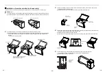
Страница 9: ...use buffering cloth or other material to not damage the unit To move the indoor unit hold the bottom face of the unit only Do not apply force to the other parts refrigerant pipe drain pan foamed parts resin parts or other parts Carry the package by two or more persons and do not bundle it with plastic band at positions other than specified Install an indoor unit as described below 1 Prior to pipin...

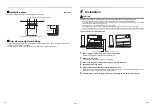
Страница 10: ...t Air intake grille Hole for wall fixing 2 with Dia 22 knockout hole Power supply cord hole Dia 26 knockout Both sides Hole for wall fixing 2 12 25 long hole left side Refrigerant pipe port Dia 130 knockout hole Refrigerant pipe connecting port Liquid side A Refrigerant pipe connecting port Gas side B Drain pipe connecting port Dia 20 Piping positional drawing Dimensions Removing the panel before ...

Страница 11: ...ket of Remote Controller Mounting Bracket of Remote Controller After installation of the Switch Cover 3 1 Insert a flat blade screwdriver or other tool into the slit two places in the bottom of the remote controller and remove the rear case 2 Install the rear case onto the switch cover using two screws unfastened in 2 4 1 Insert the remote controller wiring to the square hole in the rear case and ...

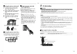
Страница 12: ...ts two at left and right Front 7 m o r l e s s 5 Drain piping CAUTION CAUTION Following the Installation Manual perform the drain piping work so that water is properly drained Apply a heat insulation so as not to cause a dew condensation Inappropriate piping work may result in water leakage in the room and wet furniture After opening the knockout hole deburr the edge Burrs adhered to opening of th...

Страница 13: ...15 88 wall thickness 1 0 mm or more REQUIREMENT When the refrigerant pipe is long provide support brackets at intervals of 2 5 3 m to clamp the refrigerant pipe Otherwise abnormal sound may be generated CAUTION CAUTION IMPORTANT 4 POINTS FOR PIPING WORK 1 Reusable mechanical connectors and flared joints are not allowed indoors When mechanical connectors are reused indoors sealing parts shall be re...

Страница 14: ...the specified wires for wiring connection to the terminals Securely fix them to prevent external forces applied to the terminals from affecting the terminals Incomplete connection or fixation may cause a fire or other trouble Connect earth wire grounding work Incomplete earthing cause an electric shock Do not connect earth wires to gas pipes water pipes lightning conductor or telephone earth wires...

Страница 15: ...ndoor unit MM UP Other than U series MM AP Wired remote controller RBC A U Other than U series Wireless remote controller kit receiver unit RBC AXU Other than U series Remote sensor TCB TC U Other than U series This letter indicates U series model This letter indicates U series model This letter indicates U series model This letter indicates U series model This letter indicates U series model In t...

Страница 16: ... group remote controllers wiring CAUTION CAUTION The remote controller wire Communication line and AC 220 V to 240 V wires cannot be parallel to contact each other and cannot be stored in the same conduits If doing so a trouble may be caused on the control system due to noise or other factor If U series models TU2C Link are combined with models other than U series TCC Link the wiring specification...

Страница 17: ...The ground of a shielded wire S The ground of a shielded wire Wire connection REQUIREMENT Connect the wires matching the terminal numbers Incorrect connection causes a trouble Pass the wires through the bushing of wire connection holes of the indoor unit Keep a margin Approx 100 mm on a wire to hang down the electrical control box at servicing or other purpose The low voltage circuit is provided f...

Страница 18: ... button is pushed indoor unit numbers in the group control change cyclically Select the indoor unit to change settings for The fan of the selected indoor unit runs The indoor unit can be confirmed for which to change settings 3 Push OFF timer button to confirm the selected indoor unit 4 Push the menu button to make Code No flash Change Code No with setting button 5 Push the menu button to make Set...

Страница 19: ...nect the indoor units by connecting the remote controller wires from the remote controller terminal blocks A B of the indoor unit connected with a remote controller to the remote controller terminal blocks A B of the other indoor unit Non polarity For address setup refer to the Installation Manual attached to the outdoor unit Set data 0000 0001 Remote controller sensor Not in use Factory default I...

Страница 20: ... to the Owner s Manual attached to the outdoor unit A forced test run can be executed in the following procedure even if the operation stops by thermostat OFF In order to prevent a serial operation the forced test run is released after 60 minutes have passed and returns to the usual operation CAUTION CAUTION Do not use the forced test run for cases other than the test run because it applies an exc...

Страница 21: ...ing test run Set the temperature to 17 C with the temp setup buttons Set the temperature to 30 C with the temp setup buttons Cooling test run Heating test run After confirming a signal receiving sound beep immediately set the temperature to 18 C with the temp setup buttons After confirming a signal receiving sound beep immediately set the temperature to 29 C with the temp setup buttons Cooling tes...

Страница 22: ...nce Replace the fan when vibration or balance is terrible Brush or wash the fan when it is contaminated Air intake discharge grilles Indoor Outdoor Dust dirt scratches Fix or replace them when they are deformed or damaged Drain pan Indoor Dust dirt clogging drain contamination Clean the drain pan and check the downward slope for smooth drainage Ceiling panel louvres Indoor Dust dirt scratches Wash...

Страница 23: ...unit side Indoor unit E06 E06 No of indoor units in which sensor has been normally received Decrease of No of indoor units I F E07 Communication circuit trouble between indoor outdoor unit Detected at outdoor unit side I F E08 E08 Duplicated indoor unit addresses Duplicated indoor unit addresses Indoor unit I F E09 Duplicated master remote controllers Remote controller E10 Communication trouble be...

Страница 24: ... 03 Comp 3 side Compressor break down Compressor inverter H02 H02 01 Comp 1 side 1 Comp 1 side 02 Comp 2 side 2 Comp 2 side 03 Comp 3 side Compressor trouble lock Compressor inverter H03 H03 01 Comp 1 side 1 Comp 1 side 02 Comp 2 side 2 Comp 2 side 03 Comp 3 side Current detect circuit system trouble Compressor inverter H04 H04 Comp 1 case thermostat operation I F H05 H05 TD1 sensor miswiring I F ...

Страница 25: ...2 Comp 2 side 2E Comp 2 side 03 Comp 3 side ALT Phase missing detection Power failure detection Inverter DC voltage trouble comp Inverter DC voltage trouble comp Inverter DC voltage trouble comp I F P07 P07 01 Comp 1 side 1C Comp 1 side 02 Comp 2 side 2C Comp 2 side 03 Comp 3 side 04 Heat sink ALT Heat sink overheat trouble Heat sink dew condensation trouble Compressor inverter I F P10 P10 Detecte...

Страница 26: ... 2 Fan 12 Comp 2 Fan2 0B Comp 1 Comp 2 Fan 13 Comp 1 Comp 2 Fan2 0C Comp 3 Fan 18 Fan1 Fan2 0D Comp 1 Comp 3 Fan 19 Comp 1 Fan1 Fan2 0E Comp 2 Comp 3 Fan 1A Comp 2 Fan1 Fan2 0F All 1B All Inverter trouble Inverter trouble Check code Wireless remote controller Check code name Judging device Central control device indication Outdoor unit 7 segment display Sensor block display of receiving unit Auxil...

Страница 27: ...ara Fuji shi Shizuoka ken 416 8521 JAPAN TCF holder TOSHIBA CARRIER EUROPE S A S Route de Thil 01120 Montluel FRANCE Hereby declares that the machinery described below Generic Denomination Air Conditioner Model type MML UP0071H E MML UP0091H E MML UP0121H E MML UP0151H E MML UP0181H E MML UP0241H E Commercial name Super Modular Multi System Air Conditioner Super Heat Recovery Multi System Air Cond...

Страница 28: ...ooms or install mechanical ventilation combined with a gas leak detection device The concentration is as given below Refrigerant Concentration Limit shall be in accordance with local regulations NOTE 1 If there are 2 or more refrigerating systems in a single refrigerating device the amounts of refrigerant should be as charged in each independent device For the amount of charge in this example The ...

Страница 29: ... 01 NO CHANGE NONE 0000 150H 0001 2500H 0002 5000H 0003 10000H 0004 Filter sign lighting time CODE NO 01 NO CHANGE NONE 0000 150H 0001 2500H 0002 5000H 0003 10000H 0004 Filter sign lighting time CODE NO 01 NO CHANGE NONE 0000 150H 0001 2500H 0002 5000H 0003 10000H 0004 Have you changed detected temp shift value If not fill check mark in NO CHANGE and fill check mark in ITEM if changed respectively...

Страница 30: ...EB99841101 ...
Отзывы: