background image

SMMS High-Wall Type

Installation Manual

– 10 –

EN

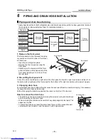
How to remove the drains cap

Clip the drain cap by needle-nose pliers and pull out.

How to fix the drains cap

1) Insert hexagonal wrench (dia. 4mm) in a centre head.

2) Firmly insert drains cap.

CAUTION

Firmly insert the drain hose and drain cap; otherwise, water may leak.

In case of right or left piping

• After scribing slits of the front panel with a knife or a marking-off pin, cut them with a pair of nippers or an 

equivalent tool.

How to remove the drain hose

1) Remove the front panel.
2) Remove the screws of drain hose.
3) Pull out the drain hose.

How to fix the drain hose

1) Put the drain hose.
2) Screw the drain hose to the indoor unit.
3) Install the front panel.

4mm

No gap

Do not apply lubricating oil (refrigerant 
machine oil) when inserting the drain cap.
Application causes deterioration and drain 
leakage from the plug.

Insert a hexagon 
wrench (4 mm)

Slit

10-EN

Содержание MMK-AP0073H

Страница 1: ...ish Manuel d installation 31 Français Installations handbuch 61 Deutsch Manuale di installazione 91 Italiano Manual de instalación 121 Español Manual de Instalação 151 Português Installatiehandleiding 181 Nederlands 211 01234356743 83 1679 342 241 Montaj Kõlavuzu 271 Türkçe 301 For commercial use Pour usage commercial Nur für gewerbliche Nutzung Per uso commerciale Para uso comercial Para uso come...

Страница 2: ...TRIC WORK 15 11 APPLICABLE CONTROLS 21 12 TEST RUN 24 13 TROUBLE SHOOTING 26 Please read this Installation Manual carefully before installing the Air Conditioner This Manual describes the installation method of the indoor unit For installation of the outdoor unit follow the Installation Manual attached to the outdoor unit ADOPTION OF NEW REFRIGERANT This Air Conditioner is a new type which adopts ...

Страница 3: ...RTS Accessory parts Others Part name Q ty Shape Installation plate 1 Wireless remote controller 1 Battery 2 Remote control holder 1 Mounting screw Ø4 25 6 Pan head wood screw Ø3 1 16 2 Screw Ø4 10 2 Heat insulator 1 Name Owner s manual Installation manual 2 EN ...

Страница 4: ...ul not to enter any gaseous matter other than the specified refrigerant into the refrigeration cycle If air or any other gas is mixed in the refrigerant the gas pressure in the refrigeration cycle becomes abnormally high and it resultingly causes pipe burst and injuries on persons Perform installation work properly according to the Installation Manual Inappropriate installation may result in water...

Страница 5: ...er dust former refrigerant or refrigerating oil does not enter the refrigerating cycle To prevent charging an incorrect refrigerant and refrigerating oil the sizes of connecting sections of charging port of the main unit and installation tools are changed from those for the conventional refrigerant Accordingly the exclusive tools are required for the new refrigerant R410A For connecting pipes use ...

Страница 6: ...ormance generate mist or dew drop or deform or damage resin parts Place where organic solvent is used nearby Place close to a machine generating high frequency Place where the discharged air blows directly into the window of the neighbour house Outdoor unit Place where noise of the outdoor unit is easily transmitted When install the outdoor unit on the boundary with the neighbour pay due attention...

Страница 7: ...sunlight to the indoor unit s wireless receiver should be avoided The microprocessor in the indoor unit should not be too close to RF noise sources For details see the owner s manual A C L For the rear left and left piping Wall Insert the cushion between the indoor unit and wall and tilt the indoor unit for better operation Do not allow the drain hose to get slack Cut the piping hole sloped slight...

Страница 8: ...pping REQUIREMENT Strictly comply with the following rules to prevent damage of the indoor units and human injury Do not put a heavy article on the indoor unit Even units are packaged Carry in the indoor unit as it is packaged if possible If carrying in the indoor unit unpacked by necessity be sure to use buffering cloth etc to not damage the unit To move the indoor unit do not apply force to the ...

Страница 9: ...ontally in the wall CAUTION When installing the installation plate with a mounting screw do not use the anchor bolt hole Otherwise the unit may fall down and result in personal injury and property damage CAUTION Failure to firmly install the unit may result in personal injury and property damage if the unit falls In case of block brick concrete or similar type walls make 5mm dia holes in the wall ...

Страница 10: ...lit on the bottom left or right side of the front panel for the bottom left or right connection with a pair of nippers 3 Changing drain hose For leftward connection bottom leftward connection and rear leftward connection s piping it is necessary to change the drain hose and drain cap Without changing the drain hose position the indoor unit will not fit to the wall How to remove the drain hose The ...

Страница 11: ...scribing slits of the front panel with a knife or a marking off pin cut them with a pair of nippers or an equivalent tool How to remove the drain hose 1 Remove the front panel 2 Remove the screws of drain hose 3 Pull out the drain hose How to fix the drain hose 1 Put the drain hose 2 Screw the drain hose to the indoor unit 3 Install the front panel 4mm No gap Do not apply lubricating oil refrigera...

Страница 12: ...pes and wrap the facing tape around them CAUTION Bind the auxiliary pipes two and power supply wiring and control wiring with facing tape tightly In case of leftward piping and rear leftward piping bind the auxiliary pipes two only with facing tape Carefully arrange pipes so that any pipe does not stick out of the rear plate of the indoor unit Carefully connect the auxiliary pipes and connecting p...

Страница 13: ...out from the left side the unit must be screwed to the installation plate 8 DRAINAGE 1 Run the drain hose sloped downwards NOTE Hole should be made at a slight downward slant on the outdoor side 2 Put water in the drain pan and make sure that the water is drained out of doors 3 When connecting extension drain hose insulate the connecting part of extension drain hose with shield pipe CAUTION Arrang...

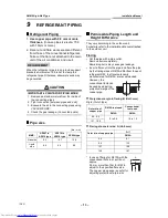
Страница 14: ...unit For details refer to the Installation Manual attached to the outdoor unit Flaring Cut the pipe with a pipe cutter Remove burrs completely Remaining burrs may cause gas leakage Insert a flare nut into the pipe and flare the pipe As the flaring sizes of R410A differ from those of refrigerant R22 the flare tools newly manufactured for R410A are recommended However the conventional tools can be u...

Страница 15: ...utdoor unit Heat insulation Heat insulation for the pipes should be done separately for the liquid side and gas side Because both of the liquid and gas side pipes become a low temperature during cooling operation sufficient heat insulation should be done to prevent condensation Heat insulator with a heat resistance of 120 C or more must be used for the gas side pipe The pipe connection section of ...

Страница 16: ...ge breaker is not installed an electric shock may be caused Be sure to use the cord clamps attached to the product Do not damage or scratch the conductive core and inner insulator of power and inter connecting wires when peeling them Use the power cord and Inter connecting wire of specified thickness type and protective devices required Never connect 220 240V power to the terminal blocks etc for c...

Страница 17: ...control communication wire Communication line Wired remote controller wiring This wiring is not required when using the supplied wireless remote controller For wiring remote controllers a 2 core non polarity wire must be used CAUTION The remote controller wire Communication line and AC220 240V wires cannot be parallel to contact each other and cannot be stored in the same conduits If doing so a tr...

Страница 18: ... 220V 60Hz 380V 415V 50Hz 380V 60Hz U1 U2 U1 U2 U3 U4 L1 L2 L3 N U5 U6 L N A B A B 380V 415V 50Hz 380V 60Hz U1 U2 U3 U4 L1 L2 L3 N U5 U6 U1 U2 L N A B A B U1 U2 L N A B A B U1 U2 L N A B Outdoor Power supply Earth terminal Earth terminal Outdoor Power supply Earth leakage breaker Earth leakage breaker Header outdoor unit Follower outdoor unit Control wiring between outdoor units Control wiring bet...

Страница 19: ... controller wire has non polarity there is no problem if connections to indoor unit terminal blocks A and B are reversed Wiring diagram A B A B Terminal block for remote controller wiring of indoor unit Wired remote controller wire Procured locally Terminal block Wired remote controller unit 18 EN ...

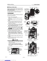
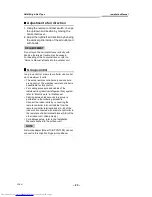
Страница 20: ...Secure the earth line with the earth screw 9 Clamp the power supply wire with the cord clamp 10 Attach the terminal cover and the air inlet grille to the indoor unit CAUTION Be sure to refer to the wiring diagram attached inside the front panel Check local electrical cords and also any specific wiring instructions and limitations Do not catch the control wire when installing the clamp base A B U1 ...

Страница 21: ...ol wire and the control wire of the flow selector unit with the cord clamp 8 Install the clamp base with a screw 9 Insert the power supply wire fully into the terminal block and secure it tightly with screws Tightening torque 1 2 N m 0 12 kgf m Secure the earth line with the earth screw 10 Clamp the power supply wire with the cord clamp 11 Insert the power supply wire fasten terminal of the flow s...

Страница 22: ... before making settings The display content for setting differs from that on the former types of remote controller RBC AMT21E AMT31E The number of CODE No has increased Procedure 1 Push button and TEMP button simultaneously for at least 4 seconds After a while the display flashes as shown in the figure Confirm that the CODE No is 10 If the CODE No is not 10 push button to erase the display content...

Страница 23: ...stop mode While SETTING is flashing no operation of the remote controller is accepted Change of lighting time of filter sign According to the installation condition the lighting time of the filter sign Notification of filter cleaning can be changed Follow to the basic operation procedure 1 2 3 4 5 6 For the CODE No in Procedure 3 specify 01 For the SET DATA in Procedure 4 select the SET DATA of fi...

Страница 24: ...red remote controller only can control a group control The wireless remote controller is unavailable for this control For cabling procedure and cables of the individual line Identical refrigerant line system refer to Electric work in this Manual Cabling between indoor units in a group is performed in the following procedure Connect the indoor units by connecting the remote controller inter unit ca...

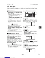
Страница 25: ... the unit as usual For the procedure of the operation refer to the attached Owner s Manual A forced test run can be executed in the following procedure even if the operation stops by thermo OFF In order to prevent a serial operation the forced test run is released after 60 minutes have passed and returns to the usual operation CAUTION Do not use the forced test run for cases other than the test ru...

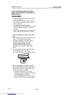
Страница 26: ... Check wiring piping of indoor and outdoor units 1 When pushing button for 10 seconds or more Pi sound is heard and the operation changes to a forced cooling operation After approx 3 minutes a cooling operation starts forcedly Check cool air starts blowing If the operation does not start check wiring again 2 To stop a test operation push button once again Approx 1 second The louver closes and the ...

Страница 27: ...history is stored in memory up to 4 troubles The history can be confirmed from both operating status and stop status Procedure 1 When pushing and buttons at the same time for 4 seconds or more the following display appears If Service check is displayed the mode enters in the trouble history mode 01 Order of trouble history is displayed in CODE No window Check code is displayed in CHECK window Indo...

Страница 28: ...emote controller display Outdoor 7 segment display Sensor block display of receiving unit Auxiliary code OPERATION TIMER PRE DEF Flash E01 Communication error between indoor and remote controller Detected at remote controller side Remote controller E02 Remote controller transmission error Remote controller E03 Communication error between indoor and remote controller Detected at indoor side Indoor ...

Страница 29: ...rror Indoor F31 F31 SIM Indoor EEPROM error I F H01 H01 01 Comp 1 side 02 Comp 2 side Compressor break down IPDU H02 H02 01 Comp 1 side 02 Comp 2 side Magnet switch error Overcurrent relay operation Compressor trouble lock MG SW Overcurrent relay IPDU H03 H03 01 Comp 1 side 02 Comp 2 side Current detect circuit system error IPDU H04 H04 Comp 1 case thermo operation I F H06 H06 Low pressure protect...

Страница 30: ...TD condition ALT Gas leak detection I F P17 P17 ALT Discharge temp TD2 error I F P19 P19 Detected outdoor unit number ALT 4 way valve inverse error I F P20 P20 ALT High pressure protective operation I F P22 P22 0 IGBT short 1 Fan motor position detective circuit error 3 Fan motor trouble C TH sensor temp error Heat sink overheat D TH sensor error E Vdc output error ALT Outdoor fan IPDU error IPDU ...

Страница 31: ...SMMS High Wall Type Installation Manual 30 EN MEMO 30 EN ...

Отзывы: