EM SERVER POWER SUPPLY REPLACEMENT
Restore Database
15-8
Installation Manual June, 2011
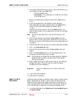
26. Verify that the OS boot Watchdog Timer is
Disabled
. If it is disabled
go to
. If it is Enabled, Highlight
Disabled
then, press the
Enter
key.
27. Highlight
Yes
then, press the
Enter
28. Press the
F10
key.
29. The system will restart.
The system has been returned to its as-shipped condition. Remember
that the IP addresses, User Names and Passwords are reset to thier
default values.
Restore Database
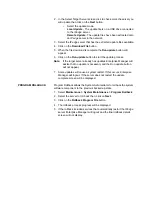
If a backup file is available use the following outline.
1. Refer to
Chapter 4 – System Installation
in this manual for the
procedures required to set the server name and IP addresses.
2. If this is a stand-alone server or Primary node go to
. If this is a
Member node go to
3. After the new system setup steps. Change the server to Member
status.
4. Access the restored server from the Primary server Enterprise
Manager.
5. Apply all licenses.
6. Restore the database. Refer to
Chapter 7 – IPedge System Backup
in the
7. Synchornize the database.
EM SERVER POWER
SUPPLY REPLACEMENT
You do not need to shut down the system to replace an EM server power
supply module. The redundant power supply feature will keep the system
up and running while you replace the failed hot-swap module. Replace
the power supply module with the same model, which can be ordered
from Toshiba.
1. The failed power supply led will change from green to amber. First
unplug the power cord from the failed power supply module.
2. To remove the failed power module, push the release tab (on the back
of the power supply) to the side and then pull the module straight out.
Refer to
.
3. The power supply wiring was designed to detach automatically when
the module is pulled from the chassis.
4. Replace the failed power module with another PWS-651-1R power
supply module.
5. Simply push the new power supply module into the power bay until
you hear a click.
6. Finish by plugging the AC power cord back into the module.
Содержание IPedge
Страница 1: ...TOSHIBA Telecommunication Systems Division Installation Manual Title Page June 2011 ...
Страница 18: ...This page is intentionally left blank ...
Страница 32: ...This page is intentionally left blank ...
Страница 46: ...This page is intentionally left blank ...
Страница 74: ...This page is intentionally left blank ...
Страница 78: ...This page is intentionally left blank ...
Страница 88: ...This page is intentionally left blank ...
Страница 92: ...This page is intentionally left blank ...
Страница 96: ...This page is intentionally left blank ...
Страница 140: ...MEDIANT 1000 CONFIGURATION IPedge Configuration 12 20 Installation Manual June 2011 ...
Страница 165: ...Server Based Call Manager Configuration Assign Users to User Groups Installation Manual June 2011 13 25 ...
Страница 187: ...EM SERVER FAN REPLACEMENT Power UP Server Installation Manual June 2011 15 11 Figure 15 2 EM Server Fan Location ...
Страница 196: ...THIS IS THE END OF THE DOCUMENT ...


