background image

15

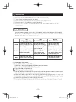
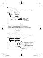
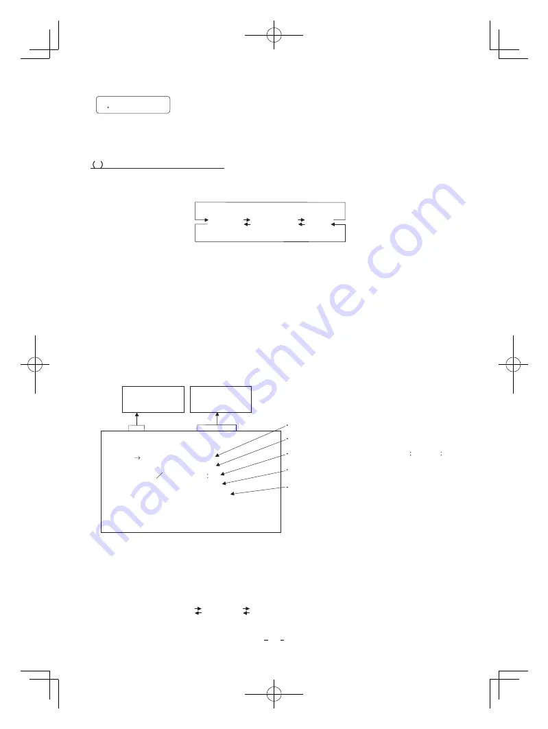
 Select the menu to change the setting by referring to the item “7.1 Using the Menus”.

 When the [MENU UP], [MENU DOWN] buttons are pressed, the “

” on the screen moves up and down. 

Move the “

” to the item whose setting you wish to change. 

 1    SHUTTER

䋨䋨

Electronic shutter

The electronic shutter has three modes; AUTO, MANUAL, SS(Synchro Scan).

Press the “Page” button to enter the Shutter Page. Use the “Data Up/Down” buttons to select the Shutter 

Mode.

AUTO 

The exposure time is controlled automatically to obtain the video level set. 

MANUAL

It is possible to select the exposure time from eight speed settings; 
OFF (1/60s : 59.94 Hz setting, 1/50s : 50 Hz setting), 1/100s, 1/125s, 1/250s, 1/500s, 1/1000s, 
1/2000s, 1/4000s. 

SS

Shutter speed can be set by the horizontal scanning time (1H) unit.

7

3   

Menus 

DATA UP

A U T O  

ޓޓ

M A N U A L    

ޓޓ

S S

DATA DOWN

䋨䋨

1

1

䋩䋩

  Changing the setting in AUTO mode 

Shutter mode    AUTO, MANUAL, SS

Video level adjustment    -100 to 100 

Peak and average ratio adjustment    00

10 to 10

00

--  1  SHUTTER  --  <FILE  A> 

Automatic shutter response speed adjustment    1 to 20 

MODE

LEVEL

Automatic shutter area selection 

PEAK

AVE

05

PRESET A, PRESET B, PRESET C, PRESET D, PRESET E

SPEED

AREA

AUTO

0

05

10

PRESET A

< MODE = AUTO> 

Move up and down 
by pressing 
MENU UP,DOWN

Select the desired 
value by pressing 
DATA UP,DOWN

(a) Changing the video level in the automatic shutter mode 

 Move the “

” to LEVEL by pressing [MENU UP], [MENU DOWN] buttons. 

  Select the video level by pressing [DATA UP], [DATA DOWN] buttons. 

- 1 0 0                           0                           1 0 0

The value increases by pressing 

[DATA UP]

The value increases by pressing 

[DATA DOWN]

Note: 

When setting a rapid shutter speed, sensitivity degrades according to the speed.  
When a discharging light such as fluorescent lamp, etc. is used for the illumination, 
the flicker may be large.

When an object is moving rapidly, the monitor  may display the image distorted and/or 
blurred. This is not a malfunction, just certain character of the rolling shutter system.

When the shutter speed setting is high, the hue may change depending on shooting 
conditions or objects.

IK-HR1S̲EN.indd   15

IK-HR1S̲EN.indd   15

2008/12/01   17:35:27

2008/12/01   17:35:27

Содержание IK-HR1S

Страница 1: ...erference at his own expense USER INSTALLER CAUTION Your authority to operate this FCC verified equipment could be voided if you make changes or modifications not expressly approved by the party responsible for compliance to Part 15 of the FCC Rules This Class A digital apparatus complies with Canadian ICES 003 Cet appareil numérique de la classe A est comforme à la norme NMB 003 du Canada Followi...

Страница 2: ... objects etc may result in fire and or electricalshock Immediately disconnect the power source and contact your dealer Avoid installing in a shower room or a bathroom This may result in fire and or electrical shock Do not operate in places where the product may get wet This may result in fire and or electrical shock Do not repair disassemble and or modify by yourself This may result in fire and or...

Страница 3: ... image or file covered by copyright is restricted to use within the scope permitted by the Copyright Law Protection of Personal Information Note the following instructions when installing Do not cover the product with any material Do not place the product on any inflammable material such as a carpet or Do not place the product in a confined space as this may cause heat to build up inside the produ...

Страница 4: ...ma correction level 4 3 Changing detail outline gain 4 4 Changing DTL B FREQ detail boost frequency 4 5 Changing master pedestal 6 6 13 7 8 8 8 9 9 10 10 12 7 2 Scene File 14 14 14 15 15 15 17 17 18 18 18 18 20 21 22 22 22 23 23 23 TABLE OF CONTENTS Limitation of Usage The product is not designed for any critical applications Critical applications means life support systems exhaust or smoke extrac...

Страница 5: ...VICE CALL 9 SPECIFICATIONS 10 EXTERNAL APPEARANCE DIAGRAM 26 26 27 7 Returning to factory settings 25 6 1 Changing RS 232C baud rate 25 6 OPTION 25 IK HR1S EN indd 5 IK HR1S EN indd 5 2008 12 01 17 35 25 2008 12 01 17 35 25 ...

Страница 6: ...e problems such as breaks in the cable and loose connections Keep the protection cap away from children as they may pose a choking hazard The protection cap protects the image sensing plane when the lens is removed from the camera head do not discard Unplug the power source before cleaning Clean with a soft dry cloth only Do not use any chemicals or chemically treated cloths Chemicals may damage c...

Страница 7: ...holes M2 The protection cap is attached on the lens mount portion After removing the cap mount the lens Be careful not to scratch or touch the optical area Used when switching the display Used when switching to the menu and when selecting the menus Select the function to be confirmed or changed on the menu Select the function to be confirmed or changed on the menu Changes the value of the function...

Страница 8: ...ely 䊶 Please use a good quality low resistance cable for the HD SDI terminal 䊶 Power supply voltage 䋺 12V DC 㫧10 Current rating 䋺 More than 830mA Ripple voltage 䋺 Less than 50mV p p Connector 䋺 HR10A 7P 4S by HIROSE electronics Co Ltd Pins 1 2 䋺 12V Pins 3 4 䋺 GND 4 2 Cautions on Connection We suggest using a C mount mega pixel lens When using other lenses the best performance of this camera may n...

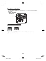
Страница 9: ...l 㪩㪜㪤㪦㪫㪜 For connecting to the REMOTE terminal use a shielded cable Connect the cable correctly or damage may occur to the camera There are DC IN 12V REMOTE terminals and HD SDI terminal BNC connector for basic connection on the rear panel Please use them as needed 1 2 3 1 4 2 3 IK HR1S EN indd 9 IK HR1S EN indd 9 2008 12 01 17 35 26 2008 12 01 17 35 26 ...

Страница 10: ... shooting conditions with no color temperature variation Notes If illumination is low white balance may not be corrected Adjustment is performed by confirming with a monitor 1 AWB Automatic White Balance Set the MODE to AWB on the WHT BAL menu Perform the C TEMP color temperature conversion setting if necessary Refer to the item 7 3 3 WHT BAL White Balance 3200K䋺Appropriate for indoor shooting 560...

Страница 11: ...llumination or use a color temperature conversion filter AWB NG C TEMP HIGH Automatic white balance adjustment cannot be performed because the color temperature is too high If the C TEMP is set to 3200K set to 5600K If the message appears with the C TEMP set to 5600K change the illumination or use the color temperature conversion filter AWB NG Automatic white balance adjustment cannot be performed...

Страница 12: ...r when the gain is increased This is not a malfunction just certain characteristics of the CMOS sensor becoming more visible When the image is dark even if the lens iris is open change the gain video gain to get the desired video level For gain adjustment of the unit MANUAL Manual OFF 0 dB modes are provided Select the mode on the GAIN menu Refer to the item 7 3 2 GAIN Video gain IK HR1S EN indd 1...

Страница 13: ...AL R GAIN 100 0 100 0 MANUAL B GAIN 100 0 100 0 ON F F O N O Gamma correction Gamma correction level 0 Detail gain 7 7 0 0 Detail boost frequency HIGH NORMAL LOW HIGH Master pedestal 128 0 127 0 ON ON OFF Color correction ON OFF R hue 15 0 15 0 R gain 15 0 15 0 G hue 15 0 15 0 G gain 15 0 15 0 B hue 15 0 15 0 B gain 15 0 15 0 Ye hue 15 0 15 0 Ye gain 15 0 15 0 Cy hue 15 0 15 0 Cy gain 15 0 15 0 Mg...

Страница 14: ...he screen by the MENU UP MENU DOWN button while the Index menu is displayed POWER ON Video signal output DISP PAGE PAGE 1 SHUTTER 2 GAIN 3 WHT BAL 4 PROCESS 5 MATRIX 6 OPTION Color bar screen Menus Index menu DISP DISP PAGE PAGE PAGE PAGE PAGE PAGE MANUAL OFF N O AWB OFF ATW MANUAL GAMMA ON GAMMA OFF AUTO MANUAL SS PAGE DISP 7 2 Scene File 䌛DATA UP䌝 FILE A ޓ ޓ FILE B ޓޓ FILE C ޓޓ FILE D ޓޓ FILE E ...

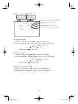
Страница 15: ...ge ratio adjustment 00 10 to 10 00 1 SHUTTER FILE A Automatic shutter response speed adjustment 1 to 20 MODE LEVEL Automatic shutter area selection PEAK AVE 05 PRESET A PRESET B PRESET C PRESET D PRESET E SPEED AREA AUTO 0 05 10 PRESET A MODE AUTO Move up and down by pressing MENU UP DOWN Select the desired value by pressing DATA UP DOWN a Changing the video level in the automatic shutter mode 㽲 M...

Страница 16: ...y pressing DATA UP The response speed becomes slower by pressing DATA DOWN 00 10 05 05 10 00 The peak value increases by pressing DATA UP The peak value decreases by pressing DATA DOWN Peak Average d Changing the automatic shutter zone area The picture area is shown by the shaded area on the screen that is divided into 64 parts 㽲 Move the 㸢 to AREA by pressing MENU UP MENU DOWN buttons 㽳 Select th...

Страница 17: ...the following mathematical formula Shutter speed s 1 67433 Hz n n 15 to 1123 integral number 1080i 59 94 Hz setting 1 56250 Hz n n 15 to 1123 integral number 1080i 50 Hz setting 1 44955 Hz n n 10 to 748 integral number 720p 59 94 Hz setting 1 37500 Hz n n 10 to 748 integral number 720p 50 Hz setting 䋨 䋨 䋨 䋨1䋮 䋮 䋮 䋮3䋩 䋩 䋩 䋩 Changing the setting in SS Synchro Scan mode Shutter mode AUTO MANUAL SS Sy...

Страница 18: ... 䋩 䋩 WHT BAL White Balance The WHT BAL has three modes AWB ATW MANUAL Move the to MODE press the DATA UP DATA DOWN and select one of the three modes AWB ATW MANUAL 㸢 䋨 䋨 䋨 䋨3䋮 䋮 䋮 䋮1䋩 䋩 䋩 䋩 Changing the setting in AWB Automatic White Balance mode White balance mode setting AWB ATW MANUAL R PAINT Red offset adjustment 10 to 10 3 WHT BAL FILE A B PAINT Blue offset adjustment 10 to 10 Selecting R PAI...

Страница 19: ...s 㽳 Select the desired value of blue paint by pressing DATA UP DATA DOWN buttons d Confirming the contents of the zone area selected by AWB 㽲 Move the 㸢 to AREA DISP by pressing MENU UP MENU DOWN buttons 㽳 Select the desired area by pressing DATA UP DATA DOWN buttons 10 0 10 DATA UP ޓ Red is increased Red is decreased ޓ DATA DOWN 10 0 10 DATA UP ޓ Blue is increased Blue is decreased ޓ DATA DOWN Th...

Страница 20: ...㸢 to R PAINT by pressing MENU UP MENU DOWN buttons 㽳 Select the desired value of red paint by pressing DATA UP DATA DOWN buttons Move up and down by pressing MENU UP DOWN Select the desired value by pressing DATA UP DOWN b Changing B PAINT Blue offset 㽲 Move the 㸢 to B PAINT by pressing MENU UP MENU DOWN buttons 㽳 Select the desired value of blue paint by pressing DATA UP DATA DOWN buttons 10 0 10...

Страница 21: ... the blue gain 㽲 Move the 㸢 to B GAIN by pressing MENU UP MENU DOWN buttons 㽳 Select the desired value of blue gain by pressing DATA UP DATA DOWN buttons Move up and down by pressing MENU UP DOWN Select the desired value by pressing DATA UP DOWN 100 0 100 DATA UP ޓ Red is increased Red is decreased ޓ DATA DOWN 100 0 100 DATA UP ޓ Blue is increased Blue is decreased ޓ DATA DOWN c Changing color tem...

Страница 22: ...uency HIGH NORMAL LOW DTL B FREQ OFF 0 0 HIGH Master pedestal setting 128 to 127 Menu when GAMMA OFF is selected 䋨 䋨 䋨 䋨4䋮 䋮 䋮 䋮2䋩 䋩 䋩 䋩 Changing gamma correction level 㽲 Move the 㸢 to GAMMA by pressing MENU UP MENU DOWN buttons 㽳 Select the desired value of gamma correction level by pressing DATA UP DATA DOWN buttons When OFF is selected in GAMMA ON OFF selection line the gamma correction level c...

Страница 23: ... thickness of the outline 㸢 to DTL B FREQ by pressing MENU UP MENU DOWN buttons 㽳 Select the detail boost frequency by pressing DATA UP DATA DOWN buttons 㽲 Move the 㸢 to M PED by pressing MENU UP MENU DOWN buttons 㽳 Select the desired value of the master pedestal by pressing DATA UP DATA DOWN buttons 䋨 䋨 䋨 䋨4䋮 䋮 䋮 䋮5䋩 䋩 䋩 䋩 Changing master pedestal 128 0 127 7 0 7 DATA UP ޓ M PED increases M PED d...

Страница 24: ...䋨5䋮 䋮 䋮 䋮1䋩 䋩 䋩 䋩 Changing Matrix color correction ON OFF 㽲 Move the 㸢 to MATRIX by pressing MENU UP MENU DOWN buttons 㽳 Select either ON or OFF by pressing DATA UP DATA DOWN buttons 䋨 䋨 䋨 䋨5䋮 䋮 䋮 䋮2䋩 䋩 䋩 䋩 Changing MATRIX setting 㽲 Move the 㸢 to the desired item by pressing MENU UP MENU DOWN buttons 㽳 Select the desired value of color by pressing DATA UP DATA DOWN buttons When matrix color correc...

Страница 25: ...t status preset status 1 If the color bar pattern or characters are displayed on the screen press the DISP button to disable the color bar pattern and character display 2 Press MENU DOWN and DATA DOWN buttons simultaneously for approx 1 second 3 The preset operation starts When the preset operation finishes the character PRESET OK is displayed for approx 1 second Only the one scene file that is se...

Страница 26: ...rizontal 33 716 kHz Vertical 59 94 Hz 1080 59 94i setting Horizontal 28 125 kHz Vertical 50 Hz 1080 50i setting Horizontal 44 955 kHz Vertical 59 94 Hz 720 59 94p setting Horizontal 37 500 kHz Vertical 50 Hz 720 50p setting Sync system Internal Sensitivity F 4 standard 2000 lx 3000K Minimum illumination 8 lx standard 50 IRE F1 4 gain 㧗18 dB gamma setting ON setting value 0 3000 K Lens mount C moun...

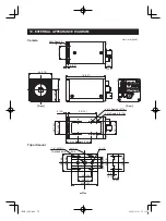
Страница 27: ... 25 0 98 25 0 98 26 1 02 22 0 87 5 0 2 26 1 02 13 4 0 53 78 3 07 2 M3 Depth 3 0 118 Front Rear Camera Tripod mount Threaded hole 25 0 98 28 1 1 50 5 1 99 11 0 43 6 0 24 6 0 24 10 8 0 43 3 5 0 14 35 1 38 33 1 3 1 4 20UNC 2 㱢5 hole 4 㱢2 2 35 1 38 25 0 98 IK HR1S EN indd 27 IK HR1S EN indd 27 2008 12 01 17 35 29 2008 12 01 17 35 29 ...

Страница 28: ...ST PROFITS LOST SAVINGS OR OTHER SPECIAL INCIDENTAL EXEMPLARY OR CONSEQUENTIAL DAMAGES WHETHER FOR BREACH OF CONTRACT TORT OR OTHERWISE OR WHETHER ARISING OUT OF THE USE OF OR INABILITY TO USE SUCH PRODUCT EVEN IF TAIS ITS PARENT COMPANY OR AN ASP HAS BEEN ADVISED OF THE POSSIBILITY OF SUCH DAMAGES OR OF ANY CLAIM BY ANY OTHER PARTY SOME STATES DO NOT ALLOW THE EXCLUSION OR LIMITATION OF INCIDENTA...

Отзывы: