1-8-7
E7M70TR
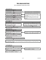
FLOW CHART NO.21
Picture does not appear normally.
Set the disc on the disc tray, and playback.
Check the periphery of JK2203 from Pin (10,11,13)
of IC1401 and replace P1(AV ASSEMBLY) if defective.
Check the periphery of JK2201 from Pin (14) of
IC1401 and replace P1(AV ASSEMBLY) if defective.
Check the periphery of JK2202 from Pin (13) of
IC1401 and replace P1(AV ASSEMBLY) if defective.
Check the periphery of JK2202 from Pin (15) of
IC1401 and replace P1(AV ASSEMBLY) if defective.
Are the video signals outputted to the specific
output terminal?
Are the Y, Pb/Cb, Pb/Cr signals outputted to the
COMPONENT OUT terminal (JK2203)?
Are the luminance signals outputted to the
S-VIDEO OUT terminal (JK2202)?
Are the chroma signals outputted to the
S-VIDEO OUT terminal (JK2202)?
No
No
No
No
Are the composite video signals outputted to
the VIDEO OUT terminal (JK2201)?
A
Yes
Are the video signals outputted to each pin of
CN1101?
Replace P2(DVD MECHANISM & DVD MAIN
BOARD ASSEMBLY).
Check the line between each pin of CN1101 and each
pin of IC1401, and replace P1(AV ASSEMBLY)
if defective.
Are the video signals shown above inputted into
each pin of IC1401?
Yes
No
No
CN1101
VIDEO-Y(I/P)
7PIN
CN1101
VIDEO-Pr/Cr
5PIN
CN1101
VIDEO-Pb/Cb
3PIN
CN1101
VIDEO-C
VIDEO-Y(I/P)
VIDEO-Pr/Cr
VIDEO-Pb/Cb
VIDEO-C
9PIN
IC1401
VIDEO-Y(I/P)
3PIN
IC1401
VIDEO-Pr/Cr
8PIN
IC1401
VIDEO-Pb/Cb
6PIN
IC1401
VIDEO-C
1PIN
CN1101
→
IC1401
7PIN
CN1101
→
IC1401
5PIN
CN1101
→
IC1401
3PIN
→
IC1401
9PIN
3PIN
8PIN
6PIN
1PIN
CN1101
Is 5V voltage applied to the Pin(4, 12) of
IC1401?
Replace P1
(AV ASSEMBLY).
Check VIDEO+5V line and replace
P1(AV ASSEMBLY) if defective.
Are the video signals outputted to each pin of
IC1401?
Yes
No
Yes
No
IC1401
VIDEO-Y(I/P)
13PIN
IC1401
VIDEO-Pr/Cr
10PIN
IC1401
VIDEO-Pb/Cb
11PIN
IC1401
VIDEO-CVBS
14PIN
IC1401
VIDEO-C
15PIN
Check the periphery of JK2203 from Pin (10,11,13)
of IC1401 and replace P1(AV ASSEMBLY) if defective.
Check the periphery of JK2201 from Pin (14) of
IC1401 and replace P1(AV ASSEMBLY) if defective.
Check the periphery of JK2202 from Pin (13) of
IC1401 and replace P1(AV ASSEMBLY) if defective.
Check the periphery of JK2202 from Pin (15) of
IC1401 and replace P1(AV ASSEMBLY) if defective.
Are the video signals outputted to the specific
output terminal?
Are the Y, Pb/Cb, Pb/Cr signals outputted to the
COMPONENT OUT terminal (JK2203)?
Are the luminance signals outputted to the
S-VIDEO OUT terminal (JK2202)?
Are the chroma signals outputted to the
S-VIDEO OUT terminal (JK2202)?
No
No
No
No
Are the composite video signals outputted to
the VIDEO OUT terminal (JK2201)?
Содержание D-R560KU
Страница 38: ...1 11 4 AV 2 4 Schematic Diagram E7M70SCAV2 NOTE BOARD MEANS PRINTED CIRCUIT BOARD ...
Страница 39: ...1 11 5 E7M70SCAV3 AV 3 4 Schematic Diagram NOTE BOARD MEANS PRINTED CIRCUIT BOARD ...
Страница 40: ...1 11 6 E7M70SCAV4 AV 4 4 Schematic Diagram NOTE BOARD MEANS PRINTED CIRCUIT BOARD ...
Страница 48: ...1 11 14 DVD MAIN 6 7 Schematic Diagram E7M70SCD6 NOTE BOARD MEANS PRINTED CIRCUIT BOARD ...
Страница 50: ...1 11 16 DTV MODULE 1 2 Schematic Diagram E7M70SCDTV1 NOTE BOARD MEANS PRINTED CIRCUIT BOARD ...
Страница 51: ...1 11 17 DTV MODULE 2 2 Schematic Diagram E7M70SCDTV2 NOTE BOARD MEANS PRINTED CIRCUIT BOARD ...
Страница 52: ...1 11 18 BE7M70F01011A BOARD AV Top View NOTE BOARD MEANS PRINTED CIRCUIT BOARD ...
Страница 56: ...1 11 22 BE7H70F01032A BOARD FRONT Bottom View BOARD FRONT Top View NOTE BOARD MEANS PRINTED CIRCUIT BOARD ...
Страница 57: ...1 11 23 BOARD POWER SWITCH Bottom View BOARD POWER SWITCH Top View BE7M70F01011C ...
Страница 62: ...1 14 3 R5NTI Push close 0 08 V 0 02 s Push Close detection Threshold level ...
Страница 69: ...1 17 4 E7M70PEX Packing Upper Side Lower Side X20 X22B X22A X5 X3 Some Ref Numbers are not in sequence Unit X1 ...
Страница 72: ......


