


Touch Screen Controller
Owner's Manual
21
-EN
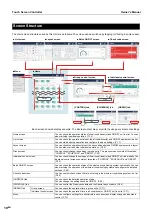
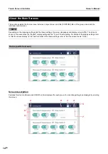
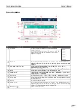
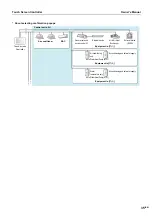
Screen description
* Only the Air to Water Heat Pump (ATW) hot water supplies, the number of FS units and LDs are not included.
No.
Name (Icon)
Functions
1
Layer Group Name
By swiping to the right or left in the Layer Group Name, you can change the selected
layer.
2
Level display area
You can select the floor to display in the floor layout.
Displays the number of air conditioners installed on each layer. *
3
Floor layout area
Tap to display the floor layout on the entire screen.
4
BACK button
Returns you to the general layout screen.
5
Unit icon
Enables you to confirm the position of a unit on the floor layout.
and
can be displayed as connected by wires to
.
If you want to display the wires, refer to the manual for the Section Configuration
Software.
6
Selected unit
Displays the operating status of the tapped unit.
7
Group display button
Tap to display the operating status of the group.
8
Group display
Displays the operating status of units group by group.
55
44
1
2
3
6
8
77
■
General layout screen
■
Detailed layout screen
■
Switch panel display
■
Group panel display
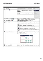
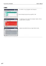
Icon
Description
Indicates indoor unit and ON/OFF unit.
Tap this icon to display the switch icon.
Indicates the Air to Water Heat Pump (ATW) of the hot water supply
function.
Tap this icon to display the switch icon.
Indicates the leak detector (LD).
Tap this icon to display the status of the leak detector (LD).
Indicates the FS unit.
Tap this icon to display the status of the FS unit.


