background image


Waste Recycling information for users:


Following information is only for EU-member states: 

The use of the crossed-out wheeled bin symbol indicates that this product  
may not be treated as general household waste.  

By ensuring this product is disposed of correctly you will help prevent  

potential negative consequences for the environment and human health, which could 

otherwise be caused by inappropriate waste handling of this product. For more detailed 

information about the take-back and recycling of this product, please contact your supplier 

where you purchased the product. 


Содержание B-SX8T SERIES

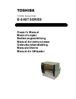
Страница 1: ...TOSHIBA Barcode Printer B SX8T SERIES Owner s Manual Mode d emploi Bedienungsanleitung Manual de instrucciones Gebruikershandleiding Manuale Utente Manual do Utilizador ...

Страница 2: ...ion against harmful interference when the equipment is operated in a commercial environment This equipment generates uses and can radiate radio frequency energy and if not installed and sed in accordance with the instruction manual may cause harmful interference to radio communications Operations of this equipment in a residential area is likely to cause harmful interference in which case the user...

Страница 3: ...TOSHIBA Barcode Printer B SX8T SERIES Owner s Manual ...

Страница 4: ... general household waste By ensuring this product is disposed of correctly you will help prevent potential negative consequences for the environment and human health which could otherwise be caused by inappropriate waste handling of this product For more detailed information about the take back and recycling of this product please contact your supplier where you purchased the product ...

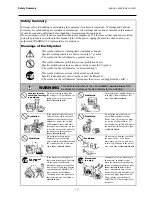
Страница 5: ...cal institution Otherwise medical equipment may be affected causing a serious accident This product may affect the operation of some implanted cardiac pacemakers and other medically implanted equipment Pace maker patients should be aware that the use of this product very close to a pacemaker might cause the device to malfunction If you have any reason to suspect that interference is taking place i...

Страница 6: ...ord plug with wet hands as this may cause electric shock If the machines share the same outlet with any other electrical appliances that consume large amounts of power the voltage will fluctuate widely each time these appliances operate Be sure to provide an exclusive outlet for the machine as this may cause fire or electric shock Do not place metal objects or water filled containers such as flowe...

Страница 7: ...s high humidity dust or gas Ensure the printer is operated on a level surface Any data stored in the memory of the printer could be lost during a printer fault Try to avoid using this equipment on the same power supply as high voltage equipment or equipment likely to cause mains interference Unplug the machine whenever you are working inside it or cleaning it Keep your work environment static free...

Страница 8: ...N E2 18 2 8 Setting an Operating Environment E2 19 2 8 1 Parameter Setting E2 20 2 8 2 Dump Mode Setting E2 36 2 8 3 BASIC Expansion Mode E2 38 2 8 4 Automatic Calibration E2 39 2 8 5 LAN Setting E2 40 2 8 6 Real Time Clock Setting E2 41 2 8 7 IP Address Setting TCP IP E2 43 2 9 Installing the Printer Drivers E2 49 2 9 1 Introduction E2 49 2 9 2 General Description E2 49 2 9 3 Installing the Print...

Страница 9: ...3 7 1 4 Effective Print Area E7 3 7 2 Ribbon E7 4 7 3 Recommended Media and Ribbon Types E7 4 7 4 Care Handling of Media and Ribbon E7 5 APPENDIX 1 MESSAGES AND LEDS EA1 1 APPENDIX 2 INTERFACE EA2 1 APPENDIX 3 POWER CORD EA3 1 APPENDIX 4 PRINT SAMPLES EA4 1 APPENDIX 5 GLOSSARIES EA5 1 INDEX CAUTION 1 This manual may not be copied in whole or in part without prior written permission of TOSHIBA TEC ...

Страница 10: ...on concerning this manual This printer has the following features Various kinds of interface Various kinds of interface are provided Standard Option Parallel Serial USB Wireless LAN LAN Expansion I O Superior hardware Clear print quality is realised by an 12 dots mm 305 dpi print head at a printing speed of 76 2 mm sec 3 inches sec 101 6 mm sec 4 inches sec or 203 2 mm sec 8 inches sec Heavy duty ...

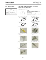
Страница 11: ...upply Holder Frame L 1 pc Supply Shaft 1 pc Wing Bolt 2 pcs NOTE As a power cord is not supplied with this printer please purchase one that meets each country s safety standard For details refer to APPENDIX 3 Contents Bar code print application Bartender ultra lite Windows Driver Owner s Manual Specifications Programming Key operation etc Product information Catalogue Safety Precautions Doc No EO2...

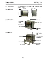
Страница 12: ...pters Dimensions in mm inches 417 16 4 282 16 4 395 15 6 LCD Message Display Media Outlet Head Lever Top Cover Power Switch 0 OFF 1 ON Right Side Cover Operation Panel USB Interface Connector Parallel Interface Connector Centronics AC Power Inlet LAN Interface Connector RS 232C Serial Interface Connector Option Wireless LAN Interface Board Option Expansion I O Interface Connector Option Media Guid...

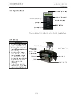
Страница 13: ...st after printing You may get burned as the Print Head becomes very hot during printing 2 Do not touch any moving parts To reduce the risk of fingers jewellery clothing etc being drawn into the moving parts be sure to load the media once the printer has stopped moving completely 3 To avoid injury be careful not to trap your fingers while opening or closing the cover POWER LED Green Ribbon Holder T...

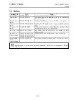
Страница 14: ...n by wireless LAN Expansion I O Board B SA704 IO QM R Installing this board in the printer allows a connection with an external device with the exclusive interface Real Time Clock B SA704 RTC QM R This module holds the current time year month day hour minute second RFID module Future Option B SX708 RFID U1 US R B SX708 RFID U1 EU R B SX708 RFID H1 QM R Installing this module enables read and write...

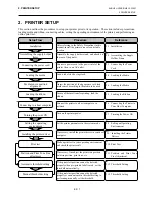
Страница 15: ...computer Make a print test in your operating environment and check the print result Print test 2 1 Installation 2 3 Connecting the Power Cord 2 4 Loading the Media 2 4 Loading the Media 2 5 Loading the Ribbon 2 6 Connecting the Printer to Your Host Computer 2 8 Setting an Operating Environment 2 10 Print Test Automatic threshold setting Manual threshold setting If necessary install the printer dri...

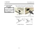
Страница 16: ...at the printer is connected to a clean source of AC Power and that no other high voltage devices that may cause line noise interference are connected to the same mains Assure that the printer is connected to the AC mains with a three prong power cable that has the proper ground earth connection 1 Assemble the Supply Holder Frame L and Supply Holder Frame R to the Supply Holder Base using the two M...

Страница 17: ... Power Cord to the printer as shown in the figure below 2 Plug the other end of the Power Cord into a grounded outlet as shown in the figure below Example of US Type Example of EU Type Power Cord Power Switch Power Cord Power Cord CAUTION As a Power Cord is not supplied with the printer please purchase an approved on that meets the safety standard of each country Refer to APPENDIX 3 ...

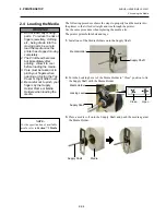
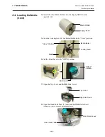
Страница 18: ...Shaft and push the media against the Media Holder 1 Do not touch any moving parts To reduce the risk of fingers jewellery clothing etc being drawn into the moving parts be sure to load the media once the printer has stopped moving completely 2 The Print Head becomes hot immediately after printing Allow it to cool before loading the media 3 Care must be taken not to pinch your fingers when opening ...

Страница 19: ...er of the Media Holder to the Close position 6 Set the Head Lever to the OPEN position 7 Open the Top Cover and the Right Side Cover 8 Open the Head Lock Plate c and turn the Pinch Roller Lever clockwise d to release the Pinch Roller Top Cover Right Side Cover Media Holder Supply Shaft Locking Lever Close Position Media Holder Media Head Lock Plate Pinch Roller Lever c d Head Lever OPEN position ...

Страница 20: ...pply Shaft Then lock the position of the media by returning the Locking Levers to the Close position 11 Feed the media until it extends past the Platen 12 Move the Media Guides inside causing the media to be automatically centred Then tighten the Media Guide Screws to secure the Media Guides Media Media Holder Frame Media Holder Media Guide Screw Media Guide Supply Holder Frame Close Open NOTE Pla...

Страница 21: ...entre Movable sensor The position of this sensor is adjustable It is intended for detecting gaps between labels black marks notches etc that are not positioned at the centre of the media Detail of Movable Sensor Detail of Fixed Sensor NOTES 1 When using the Movable sensor choose the Movable sensor for the parameter setting in the system mode Section 2 8 1 Parameter Setting The Fixed sensor has bee...

Страница 22: ...r is used to detect the print start position Looking inside of the Media Outlet move the Movable Sensor by rotating the Adjustment Knob until the Feed Gap Sensor aligns with a gap The right side hole indicates the position of the Feed Gap Sensor Media Outlet Adjustment Knob Left side hole Black Mark Sensor Right side hole Feed Gap Sensor Forward Backward NOTE Adjustment Knob Forward Moves toward t...

Страница 23: ... turn the media back on it s self and feed it under the print head 2 Move the Movable Sensor by rotating the Adjustment Knob until the Black Mark Sensor aligns with a black mark The left side hole indicates the position of the Black Mark Sensor NOTE Be sure to set the Black Mark Sensor to detect the centre of the black mark otherwise a paper jam or no paper error may occur Media Left side hole Bla...

Страница 24: ...ode is provided below In the batch mode the media is continuously printed and fed until the number of labels tags specified in the issue command have been printed 1 Pull the media past the media outlet 2 Turn the Pinch Roller Lever counterclockwise to lock the Pinch Roller 3 Close the Top Cover and Right Side Cover Batch mode Media Outlet Right Side Cover Top Cover Pinch Roller Lever ...

Страница 25: ... backing paper between the Backing Paper Holder and the Strip Roller Then release the Backing Paper Release Bar 3 Turn the Pinch Roller Lever counterclockwise to lock the Pinch Roller 4 Close the Top Cover and Right Side Cover Strip mode Option When the Backing Paper Release Bar is released it is automatically closed by the spring Care must be taken not to pinch your fingers or hands WARNING Backi...

Страница 26: ...Top Cover and Right Side Cover Cut mode Option CAUTION 1 When using a label stock be sure to cut the gaps Cutting labels will cause the glue to stick to the cutter which may affect the cutter quality and shorten the cutter life 2 Use of tag paper which thickness exceeds specified value may affect the cutter life For the specification of the media refer to Section 7 1 Media The cutter is sharp so c...

Страница 27: ...or thickness Label or Thin media 1 If a clear print cannot be obtained change the position to d Tag paper or Thick paper 2 If a clear print cannot be obtained change the position to c 16 If the loaded media is direct thermal media with a chemically treated surface the media loading procedure is now completed If the media is normal media it is also necessary to load a ribbon Refer to Section 2 5 Lo...

Страница 28: ...ailure to do this may cause missing dots by static electricity or other print quality problems 1 Do not touch any moving parts To reduce the risk of fingers jewellery clothing etc being drawn into the moving parts be sure to load the ribbon once the printer has stopped moving completely 2 The print head becomes hot immediately after printing Allow it to cool before loading the ribbon 3 To avoid in...

Страница 29: ...bbon core with the protrusion of the Ribbon Holder 5 Fit the core of the Ribbon Take up Roll into the Ribbon Holders Take up side aligning the notch of the ribbon core with the protrusion of the Ribbon Holder Ribbon Holder Supply Side Ribbon Supply Roll Ribbon Supply Roll Notch Ribbon Core Ribbon Holder Take up Side Ribbon Take up Roll Fit the protrusion into the notch Fit the protrusion into the ...

Страница 30: ...the ribbon when printing Printing with a wrinkled ribbon will lower the print quality 2 When a ribbon end is detected RIBBON ERROR message will appear on the display and the ERROR LED will illuminate 3 When disposing of the ribbons please follow the local rules 4 For the specification of available ribbon refer to Section 7 2 Ribbon 5 When using a non transparent ribbon choose the Non trans ribbon ...

Страница 31: ...ector and one of your host computer s COM ports Option Wireless LAN using an optional Wireless LAN board Option For details of each interface refer to APPENDIX 2 After connecting the necessary interface cables set an operating environment of the printer Refer to Section 2 8 1 Parameter Setting The diagram below shows all the possible cable connections to the current version of the printer Standard...

Страница 32: ... below Note that is the power ON side of the switch 2 Check that the ON LINE message appears in the LCD Message Display and that the ON LINE and POWER LED Green are illuminated CAUTION Use the power switch to turn the printer On Off Plugging or unplugging the Power Cord to turn the printer On Off may cause fire an electric shock or damage to the printer NOTES 1 If a message other than ON LINE appe...

Страница 33: ... to Section 2 8 3 BASIC Expansion Mode 6 AUTO CALIB This menu is used to enable or disable the automatic calibration function Refer to Section 2 8 4 Automatic Calibration 7 LAN This menu is used to enable or disable the LAN communication and SNMP Refer to Section 2 8 5 LAN Setting 8 RTC SET This menu is used to set the date and time of the real time clock enable or disable the low battery check an...

Страница 34: ...Flow control code selection 8 LCD language selection 9 Auto forward wait selection 10 Head up cut selection 11 Ribbon saving function selection 12 Control code selection 13 Ribbon Type Selection 14 Strip wait status selection 15 FEED key function selection 16 KANJI code selection 17 EURO code selection 18 Auto print head check selection 19 Centronics ACK BUSY timing selection 20 Web printer functi...

Страница 35: ...ss the PAUSE key twice Use the FEED or RESTART key to select a desired option After selecting a character zero press the PAUSE key NOTE Be careful if the printer is turned off without pressing the PAUSE key the selected value does not become effective 2 PARAMETER SET FONT CODE PC 850 2 PARAMETER SET ZERO FONT 0 ZERO FONT 0 ZERO FONT Ø RESTART FEED Without slash With slash NOTE The following fonts ...

Страница 36: ...n After selecting a baud rate press the PAUSE key 4 Data Length Selection This parameter is to choose a communication data length of the RS 232C interface 7 bits is used when transmitting alphanumeric data only 8 bits is used to when transmitting special characters Be sure to match a setting with a host computer When 2 PARAMETER SET appears press the PAUSE key until the following display appears U...

Страница 37: ...XOFF AUTO READY BUSY XON XOFF READY BUSY RTS XON XOFF mode XON XOFF READY BUSY DTR mode READY BUSY DTR mode XON XOFF mode RTS mode 2 PARAMETER SET PARITY NONE PARITY EVEN PARITY ODD RESTART FEED PARITY NONE NOTE The following is the detailed descriptions for each transmission control code 1 XON XOFF AUTO At the power on time the printer outputs XON At the power off time the printer outputs XOFF 2 ...

Страница 38: ...ing When 2 PARAMETER SET appears press the PAUSE key until the following display appears Use the FEED or RESTART key to select a desired option After selecting an auto forward wait press the PAUSE key 2 PARAMETER SET LCD ENGLISH RESTART FEED ENGLISH ITALIAN JAPANESE SPANISH DUTCH FRENCH GERMAN 2 PARAMETER SET FORWARD WAIT OFF RESTART FEED FORWARD WAIT OFF Not activated FORWARD WAIT ON Activated NO...

Страница 39: ...ection This parameter is to choose whether to activate the head up action in the cut issue This function prevents ribbon smudges by raising the print head during a reverse feed to the print start position When 2 PARAMETER SET appears press the PAUSE key until the following display appears Use the FEED or RESTART key to select a desired option After selecting the head up action in cut issue press t...

Страница 40: ...ress the PAUSE key until the following display appears Use the FEED or RESTART key to select a desired option 2 PARAMETER SET RBN SAVE ON TAG 2 PARAMETER SET CODE AUTO CODE AUTO CODE ESC LF NUL RESTART FEED CODE CODE MANUAL Automatic selection Manual selection Manual selection Control codes should be specified RESTART FEED RBN SAVE ON LBL Activated When the head lever is set to position 1 RBN SAVE...

Страница 41: ...TROL CODE3 screen Press the PAUSE key after setting the control code for Control Code 3 13 Ribbon Type Selection This parameter is to choose a ribbon type to be used When 2 PARAMETER SET appears press the PAUSE key until the following display appears Use the FEED or RESTART key to select a desired option After selecting a ribbon type press the PAUSE key CONTROL CODE1 CONTROL CODE2 CONTROL CODE3 PA...

Страница 42: ... to choose the function of the FEED key When 2 PARAMETER SET appears press the PAUSE key until the following display appears Use the FEED or RESTART key to select a desired option After selecting the FEED key function press the PAUSE key 2 PARAMETER SET FEED KEY FEED FEED KEY FEED FEED KEY PRINT RESTART FEED The FEED key will feed one media when pressed The FEED key will print the data in the Imag...

Страница 43: ...arameter is to choose a Euro code When 2 PARAMETER SET appears press the PAUSE key until the following display appears Use the FEED or RESTART key to select a desired option After selecting a Euro code press the PAUSE key NOTE Kanji code selection is not supported by the QM model as the Kanji ROMs are not installed 2 PARAMETER SET EURO CODE B0 NOTE Pressing the FEED or RESTART key causes 1 byte ch...

Страница 44: ...E key until the following display appears Use the FEED or RESTART key to select a desired option After selecting an ACK BUSY timing press the PAUSE key NOTES 1 It is recommended that this function should be activated when high quality printing such as bar codes printing is required Otherwise choose OFF 2 When a broken element is found the printer stops displaying HEAD ERROR The error state can be ...

Страница 45: ... key 21 Media Sensor Selection This parameter is to choose the media sensor type to be used When 2 PARAMETER SET appears press the PAUSE key until the following display appears Use the FEED or RESTART key to select a desired option After selecting the media sensor type press the PAUSE key NOTE When WEB PRINTER ON is selected the status of the printer connected in a network can be checked through t...

Страница 46: ...press the PAUSE key until the following display appears Use the FEED or RESTART key to select a desired option After selecting the Input Prime press the PAUSE key 23 Expansion I O Interface Type Selection This parameter is to choose a type of the Expansion I O interface operating mode This parameter should be set depending on the expansion I O control specification of the device to be connected vi...

Страница 47: ... PAUSE key until the following display appears Use the FEED or RESTART key to select a desired option After selecting a Label End Ribbon End type press the PAUSE key NOTE If the printer and the PC are connected by USB plug play will be automatically enabled regardless of the setting of this parameter 2 PARAMETER SET LBL RBN END TYP1 LBL RBN END TYP1 LBL RBN END TYP2 RESTART FEED TYPE1 When a label...

Страница 48: ...s press the PAUSE key until the following display appears This parameter is fixed to OFF Press the PAUSE key 27 Reverse Feed Speed Selection This parameter is to choose a reverse feed speed In the strip issue the back feed speed of 3 sec may cause a shortage of feed amount due to a lack of torque slippery media surface etc In such case reduce the back feed speed to 2 sec to secure the feed amount ...

Страница 49: ...to R0 Press the PAUSE key 30 Stabilizer Function Selection This parameter is to choose whether to use the stabilizer function The stabilizer function reduces the sound of printing When 2 PARAMETER SET appears press the PAUSE key until the following display appears Use the FEED or RESTART key to select a desired option After selecting the stabilizer function press the PAUSE key 2 PARAMETER SET MAXI...

Страница 50: ...E B SX8T Vx x Turn off the power and then on PAUSE BUFFER RS 232C BUFFER NETWORK RESTART FEED BUFFER BASIC 1 BUFFER CENTRO BUFFER BASIC 2 BUFFER USB 4 DUMP MODE PRINT ON DEMAND PRINT ON DEMAND RESTART FEED Prints 166 lines of data approx 50cm then stops To print the subsequent data choose a printing method again and press the PAUSE key Prints all data in the receive buffer then stops PRINT ALL BAS...

Страница 51: ...0 2C 30 30 33 30 2C 30 36 36 30 0 0020 0030 0660 2C 30 2C 32 7C 7D 7B 4C 43 3B 30 30 37 30 2C 30 0 2 LC 0070 0 30 32 30 2C 30 30 37 30 2C 30 36 36 30 2C 30 2C 020 0070 0660 0 39 7C 7D 7B 4C 43 3B 30 30 35 30 2C 30 30 32 30 9 LC 0050 0020 44 45 46 47 48 49 4A 7C 7D 7B 50 43 31 30 3B 30 DEFGHIJ PC10 0 33 35 30 2C 30 34 30 30 2C 31 2C 31 2C 4B 2C 30 350 0400 1 1 K 0 30 2C 42 3D 41 42 43 44 65 66 67 6...

Страница 52: ...cute the BASIC expansion mode program under the following conditions The BASIC expansion mode program has already been loaded The BASIC enable setting mode is selected The basic expansion mode ends when the basic expansion program is exited When 5 EXPAND MODE appears press the PAUSE key When the PAUSE key is pressed BASIC program is executed 5 EXPAND MODE NOTE For the BASIC enable setting mode ref...

Страница 53: ...LIB OFF OFF ON REFLECT RESTART FEED Not activated Activated Feed gap sensor ON TRANS Activated Black mark sensor NOTES 1 This function is available only when the media pitch is 10 0 mm to 150 0 mm 2 When this function is activated the media length effective print length and sensor type specified in the command are ignored 3 When the printer cannot find a print start position properly it will conti...

Страница 54: ...LAN Setting Mode In the LAN Setting Mode whether to enable the LAN communication and SNMP or not is selectable When 7 LAN appears press the PAUSE key Use the FEED or RESTART key to select a desired option After selecting the LAN setting press the PAUSE key 7 LAN ON SNMP ON OFF ON SNMP OFF RESTART FEED LAN is disabled LAN and SNMP are enabled ON SNMP ON LAN is enabled but SNMP is disabled ...

Страница 55: ...t the Year Month and Day in order When 8 RTC SET appears press the PAUSE key Press the PAUSE key to set the date After selecting the date press the PAUSE key 2 Time Setting This parameter is to set the Hour Minute and Second in order Press the PAUSE key to set the time After selecting the time press the PAUSE key 8 RTC SET DATE 05 01 01 8 RTC SET DATE Y 06 01 01 8 RTC SET DATE M 06 03 01 8 RTC SET...

Страница 56: ...WAL BATCH RESTART FEED Batch print is possible However the same time is printed on the all media issued in a batch because the real time clock data is read only for the first media A real time can be printed on each media However the printer needs to stop the motion before printing each media to read the real time clock data RENEWAL PAGE NOTE 1 Be sure to load the battery and set the low battery c...

Страница 57: ...ustment of a print start position cut position etc 4 TEST PRINT This menu is used to perform print tests 5 SENSOR ADJ This menu is used to check the sensor statuses and adjust each sensor 6 RAM CLEAR This menu is used to perform a RAM clear DO NOT USE this menu 7 IP ADDRESS This menu is used to set an IP address 8 BASIC This menu is used to enable the printer to use Basic program 9 FOR FACTORY Thi...

Страница 58: ...s Now the printer is in the System Mode for system administrators 3 Press the FEED or RESTART key until 7 IP ADDRESS appears on the LCD Message Display 4 Press the PAUSE key to enter the IP Address Setting Mode The IP Address Setting Mode contains the following sub menus To enter each sub menu press the PAUSE key 7 IP ADDRESS PRINTER IP ADRES 7 IP ADDRESS GATEWAY IP ADRES 7 IP ADDRESS SUBNET MASK ...

Страница 59: ... 7 IP ADDRESS GATEWAY IP ADRES PAUSE PAUSE NOTES 1 Set each 3 digit value by using the RESTART or FEED key RESTART key Increment FEED key Decrement Range 0 to 255 2 Press the PAUSE key to move the cursor to the next 3 digit value 3 After the last 3 digit value is set press the PAUSE key to go to Gateway IP Address Setting 7 IP ADDRESS GATEWAY IP ADRES 7 IP ADDRESS 192 168 010 020 7 IP ADDRESS 192 ...

Страница 60: ...et Port Setting NOTES 1 Pressing the PAUSE key while PORT ON 08000 is displayed allows you to set the port number 2 Set a number for each digit by using the RESTART or FEED key RESTART key Increment FEED key Decrement Range 00000 to 65535 A number exceeding 65535 will be automatically corrected to 65535 3 Be careful not to set the same port number that other applications are using 4 Press the PAUS...

Страница 61: ...ent FEED key Decrement 3 Press the PAUSE key to enter the next byte Repeat this until 16th byte is entered 4 A DHCP ID can be used to check what IP address is assigned to which client on a DHCP server If a DHCP ID is not assigned MAC address of a network device LAN card or LAN interface board will be notified to the server as a DHCP ID instead A DHCP ID is a 16 byte character string As FFH hex cod...

Страница 62: ... U e u 6 6 F V f v 7 7 G W g w 8 8 H X h x 9 9 I Y i y A J Z j z B K k C L l D M m E N n F O _ o SP Space Example To enter TOSHIBA in Hex code 54 4F 53 48 49 42 41 When the system mode settings have been completed turn off the printer 7 IP ADDRESS DHCP HOST NAME MODE ASCII PAUSE PAUSE 7 IP ADDRESS Enter a character or a value for each of 1st byte to 16th byte sequentially using the FEED or RESTART...

Страница 63: ...9 2 General Description 1 Features Once you install the TOSHIBA printer driver on your Windows host computer you can use the TOSHIBA bar code printer as well as the easy to use general printers You can use this printer by connecting a parallel interface cable printer cable a USB cable or a LAN cable to your host computer 2 System Requirements To install the TOSHIBA printer driver on your host comp...

Страница 64: ...re for the parallel interface and also perform the following 1 In the procedure select LPT1 for the port 2 After installation of the printer driver is completed add the LAN port by referring to Section 2 9 5 Adding Deleting a LAN Port and specify the LAN port 1 Parallel Interface To use the parallel interface the following settings are required after installing the printer driver For Windows 98 Me...

Страница 65: ...10 QQ B 492R TH10 QQ B 492L TH10 QP B 492R TH10 QP TEC B 572 B 572 QQ B 572 QQ US B 572 QP TEC B 672 B 672 QQ B 672 QQ US B 672 QP TEC B 682 B 682 TS10 QQ B 682 TS10 QQ US B 682 TS10 QP TEC B 852 B 852 TS12 QQ B 852 TS12 QQ US B 852 TS12 QP TEC B 852 R B 852 TS22 QQ R B 852 TS22 QP R TEC B 872 B 872 QQ B 872 QQ US B 872 QP TEC B 882 B 882 TS10 QQ B 882 TS10 QQ US B 882 TS10 QP TEC B SA4G B SA4TM G...

Страница 66: ...ou install the printer driver for the first time this screen is not displayed 7 Select the port to be used for printing from the Available ports list then click on the Next button 8 Change the printer name if necessary and select whether or not you use the printer as the default printer Yes or No Click on the Finish button 9 The printer driver is installed When installation is completed the new pr...

Страница 67: ...Q US B 472 GH12 QQ B 472 QP TEC B 472 CN B 472 GH12 CN B 472 GH14 CN TEC B 482 B 482 TS10 QQ B 482 TS10 QQ US B 482 TS10 QP TEC B 492 B 492L TH10 QQ B 492R TH10 QQ B 492L TH10 QP B 492R TH10 QP TEC B 572 B 572 QQ B 572 QQ US B 572 QP TEC B 672 B 672 QQ B 672 QQ US B 672 QP TEC B 682 B 682 TS10 QQ B 682 TS10 QQ US B 682 TS10 QP TEC B 852 B 852 TS12 QQ B 852 TS12 QQ US B 852 TS12 QP TEC B 852 R B 85...

Страница 68: ...e printer as the default printer Yes or No Click on the Next button 11 Select whether or not the printer will be shared with other network users Shared or Not shared Click on the Next button 12 Select whether or not the test page will be printed Yes or No then click on the Finish button 13 If the Digital Signature Not Found screen is displayed click on the Yes button 14 When the Completing the Add...

Страница 69: ...m s plug and play function 1 Turn the printer ON then connect it to your host computer with the USB cable The New Hardware Found dialog box is displayed and USB Device is detected 2 After a while the Add New Hardware Wizard dialog box is displayed Select Specify the location of the driver Advanced then click on the Next button Windows 98 Me ...

Страница 70: ...56 3 Select Search for the best driver for your device Recommended Mark the Specify a location checkbox then click on the Browse button Specify driver folder then click on the Next button 4 Check to see that the USB Printing Support driver is detected then click on the Next button ...

Страница 71: ...n which indicates the USB Printing Support driver has been installed is displayed click on the Finish button 6 After a while TEC B SA4T is detected as a new hardware 7 The Add New Hardware Wizard dialog box is displayed Select Specify the location of the driver Advanced then click on the Next button ...

Страница 72: ...s E2 58 8 Select Search for the best driver for your device Recommended Mark the Specify a location checkbox then click on the Browse button Specify driver folder then click on the Next button 9 Check to see that the TEC B SA4T driver is detected then click on the Next button ...

Страница 73: ... if necessary and select whether or not you use the printer as the default printer Yes or No Click on the Finish button 11 When the screen which indicates TEC B SA4T has been installed is displayed click on the Finish button 12 When installation is completed the new printer icon is added in the Printers folder ...

Страница 74: ...tomatically installed 4 After a while for Windows XP TEC B SA4T is detected as a new device For Windows 2000 Unknown device is detected as a new device In both cases perform the following steps though dialog boxes for Windows XP are used 5 The Found New Hardware Wizard dialog box is displayed Select No not this time then click on the Next button Windows 2000 XP NOTE When plug and play printer inst...

Страница 75: ...t Install from a list or specific location Advanced then click on the Next button 7 Select Search for the best driver in these locations Mark the Include this location in the search checkbox then click on the Browse button Specify the driver folder in the CD ROM then click on the Next button ...

Страница 76: ...vers E2 62 8 When the dialog box below is displayed click on the Continue Anyway button 9 When the Completing the Found New Hardware Wizard screen is displayed click on the Finish button 10 When installation is completed the new printer icon is added in the Printers folder ...

Страница 77: ...l control access privilege concerning the printer settings 2 Select Settings Printers from the Start menu to open the printer folder 3 Right click on the printer driver icon to be deleted then select Delete The confirmation message is displayed 4 Click on the Yes button to delete 5 After the printer icon is deleted select Server Properties from File menu of the Printers folder 6 Select the printer...

Страница 78: ... a LAN port 1 Adding a LAN Port 1 Right click on the printer icon Select Properties to open the printer Properties dialog box 2 Select the Details tab and click on the Add Port button The Add Port dialog box is displayed 3 Select Other Select Seagull Scientific TCP IP Port from the list then click on the OK button 4 On the Add Seagull TCP IP Port dialog box enter the name or IP address the port nu...

Страница 79: ...added to the Print to the following port s list 2 Deleting a LAN Port 1 Right click on the printer icon Select Properties to open the printer Properties dialog box 2 Select the Details tab and click on the Delete Port button 3 Select the port to be deleted then click on the OK button 4 When deletion of the port is completed the port is also deleted from the Print to the following port list 1 Right...

Страница 80: ... uninstall the previous version of the printer driver Or the printer driver is not upgraded properly 2 Others If your operating system is Windows 2000 or Windows XP when plug and play printer installation in progress is stopped be sure to delete the printer detected and displayed on the Device Manager tab of the System Properties dialog box Before uninstalling the printer driver be sure to complet...

Страница 81: ...r Driver please refer to the Help for Windows Printer Drivers screen 1 Open the Properties screen of the Printer Driver 2 Clicking on the About tab causes the following screen to appear Click on the Help button 3 The Help for Windows Printer Drivers screen appears This screen will provide how to use the printer driver About tab Help button ...

Страница 82: ...play of the Printer Driver s Properties Screen Print Method Direct thermal or thermal transfer is selectable Sensor Media sensor type is selectable Issue Mode Batch or strip is selectable Cut Whether to use the cutter or not is selectable Fine Adjustment Adjustment values for the feed amount cut strip position etc can be set 2 Confirm the print test result When a print start position cut strip pos...

Страница 83: ...ternal Equipment Interface Specification stored in the CD ROM Regarding how to use the Printer Driver refer to the Help for the Windows Printer Drivers screen To gain maximum performance and life from the Cutter Module or Strip Module periodic cleaning is required Before starting a cleaning be sure to TURN OFF the printer to avoid risk of injury For details of cleaning refer to Section 4 1 5 Optio...

Страница 84: ...ne adjusted 3 Reverse Feed Amount Fine Adjustment Reverse feed amount is fine adjusted 4 X coordinate Fine Adjustment X coordinate of a print position is fine adjusted 5 Print Tone Fine Adjustment Thermal transfer Print tone is fine adjusted for thermal transfer mode 6 Print Tone Fine Adjustment Thermal direct Print tone is fine adjusted for thermal direct mode 7 Ribbon Motor Drive Voltage Fine Ad...

Страница 85: ...ES Choose a desired value by using the RESTART or FEED key Pressing the FEED key one time causes a 0 1mm change up to 50 0 mm Pressing the RESTART key one time causes a 0 1mm change up to 50 0 mm One label Print Start Position Print Start Position 3mm 3mm Feed Direction Feed Direction Print Start Position One label Feed Direction One label Example of Print Start Position Fine Adjustment When setti...

Страница 86: ...mm CUT ADJ 0 1mm CUT ADJ 0 1mm NOTES Choose a desired value by using the RESTART or FEED key Pressing the FEED key one time causes a 0 1mm change up to 50 0 mm Pressing the RESTART key one time causes a 0 1mm change up to 50 0 mm Cut Position Cut Position Feed Direction 3mm 3mm Feed Direction Feed Direction Cut Position Example of Cut Position Fine Adjustment When setting 3 0 mm Compared with 0 0m...

Страница 87: ...0 mm Compared with 0 0mm position the stop position after printing is shifted forward When setting 0 0 mm When setting 3 0 mm Compared with 0 0mm position the stop position after printing is shifted backward Label Print Head Platen Strip Plate Backing Paper 3mm Stop position after printing Stop position after printing Stop position after printing 3mm ...

Страница 88: ... 9 9 mm Example of Reverse Feed Amount Fine Adjustment When setting 3 0 mm Compared with 0 0mm position the print start position after a reverse feed is shifted forward When setting 0 0 mm When setting 3 0 mm Compared with 0 0mm position the print start position after a reverse feed is shifted backward RESTART FEED BACK ADJ 9 9mm BACK ADJ 9 8 mm BACK ADJ 0 0mm BACK ADJ 9 8mm BACK ADJ 9 9mm BACK AD...

Страница 89: ...9 mm Pressing the RESTART key one time causes a 0 1mm change up to 99 9 mm Example of X Coordinate Fine Adjustment When setting 50 0 mm Compared with 0 0mm position the print position is shifted to the left When setting 0 0 mm When setting 50 0 mm Compared with 0 0mm position the print position is shifted to the right 3 ADJUST SET X ADJUST 5 0mm RESTART FEED X ADJUST 99 9mm X ADJUST 99 8mm X ADJUS...

Страница 90: ... this menu press the PAUSE key Print Tone Fine Adjustment NOTES Choose a desired value by using the RESTART or FEED key Pressing the FEED key one time causes a 1 tone change up to 10 tones Pressing the RESTART key one time causes a 1 tone change up to 10 tones 3 ADJUST SET TONE ADJ T 3 RESTART FEED TONE ADJ T 10 TONE ADJ T 9 TONE ADJ T 0 TONE ADJ T 9 TONE ADJ T 10 Darker Lighter Standard TONE ADJ ...

Страница 91: ...Motor Voltage Fine Adjustment RESTART FEED RBN ADJ FW 0 RBN ADJ FW 1 RBN ADJ FW 2 RBN ADJ FW 14 RBN ADJ FW 15 Motor Torque High Low 3 ADJUST SET RBN ADJ FW 10 RBN ADJ BK 10 RBN ADJ BK 9 RBN ADJ BK 8 RBN ADJ BK 14 RBN ADJ BK 15 Motor Torque High Low RESTART FEED 3 ADJUST SET RBN ADJ BK 5 NOTES Choose a desired value by using the RESTART or FEED key Pressing the FEED key one time causes a 1 step cha...

Страница 92: ...he centre of a black mark 3 Press the PAUSE key 4 The printer enters the pause mode 5 Press and hold the PAUSE key in the pause state until the following screen appears 6 The sensor type is displayed 7 Select the sensor to be adjusted by using the FEED key 8 Press and hold the PAUSE key until more than 1 5 labels tags have been issued The media will continue to be fed until the PAUSE key is releas...

Страница 93: ...ted by the Print Head Thermistor and the Ambient Thermistor are displayed 2 Black Mark Sensor Status Display Voltage being detected by the Black Mark Sensor is displayed 3 Black Mark Sensor Adjustment Using the media actually used a media level voltage is stored 4 Feed Gap Sensor Status Display Voltage being detected by the Feed Gap Sensor is displayed 5 Feed Gap Sensor Adjustment Using the media ...

Страница 94: ...ut 3 seconds aligning a blank part of print area with the Feed Gap Sensor 3 When storing a media level voltage is completed an asterisk is displayed on the right side of a voltage Press the PAUSE key 4 The display changes as shown on the left NOTES 1 When measuring a voltage of a blank area be careful not to align a pre print with the sensor by mistake 2 Confirm that there is at least 0 7V differe...

Страница 95: ...Sensor are displayed 3 Press and hold the RESTART or FEED key for about 3 seconds 4 When storing a no media level voltage is completed an asterisk is displayed on the right side of a voltage Press the PAUSE key 5 The message returns to 5 SENSOR ADJ Manual Threshold Setting Then set the calculated threshold voltage in the Parameter Fine Adjustment mode 1 While 5 SENSOR ADJ is displayed press the FE...

Страница 96: ...check for a proper operation issue the pre printed media in online If an error still occurs even after a manual threshold setting change the threshold voltage a little and retry NOTE Pressing the FEED key one time causes a 0 1V change up to 0 0V Pressing the RESTART key one time causes a 0 1V change up to 4 0V Black Mark Sensor Feed Gap Sensor RESTART FEED THRESHOLD R 4 0V THRESHOLD R 3 9V THRESHO...

Страница 97: ...us Up to 32 characters can be displayed on two lines There are three LEDs on the Operation Panel LED Illuminates when Flashes when POWER The printer is turned on ON LINE The printer is ready to print The printer is communicating with your computer ERROR Any error occurs with the printer The ribbon is nearly over See NOTE 1 There are three keys on the operation panel PAUSE Used to stop printing tem...

Страница 98: ...ion clears the print data sent from the computer to the printer and returns the printer to an idle condition 1 The printer is turned on standing by or printing 2 To stop printing or clear the data sent from the computer press the PAUSE key The printer stops printing 3 Press and hold the RESTART key for 3 seconds or longer 4 Press the PAUSE key The data sent from the computer will be cleared and th...

Страница 99: ...RNING 1 Be sure to disconnect the power cord before performing maintenance Failure to do this may cause an electric shock 2 To avoid injury be careful not to pinch your fingers while opening or closing the cover and print head block 3 The print head becomes hot immediately after printing Allow it to cool before performing any maintenance 4 Do not pour water directly onto the printer CAUTION 1 Do n...

Страница 100: ...ler Lever clockwise to release the Pinch Roller 6 Remove the ribbon and media from the printer 7 Set the Head Lever to the Position 2 8 Remove the White Screw and detach the Ribbon End Sensor Plate in the direction of the arrows Platen Pinch Roller Lever White Screw Ribbon End Sensor Plate Ribbon End Sensor Plate 1 2 CAUTION Do not pull hard on the Ribbon End Sensor Plate Doing so may damage the R...

Страница 101: ... y place it in position and raise the both Pinch Roller Plates CAUTION When re installing the Pinch Roller Ass y on the printer remove the slack of the Ribbon End Sensor Harness as far as possible by pushing it into the opening indicated by the arrow Failure to do this may cause the harness to be caught by the Ribbon End Sensor Plate resulting in a printer failure Pinch Roller Ass y Pinch Roller A...

Страница 102: ... to the printer 1 Engage the notches on the both sides of the Ribbon End Sensor Plate with the Positioning Pins of the printer 2 Fit the tip of the Pinch Roller Plates into the slot in the Ribbon End Sensor Notch Ribbon End Sensor Plate Positioning Pin Positioning Pin Slot Pinch Roller Plate Ribbon End Sensor Plate Slot ...

Страница 103: ...Lever clockwise to release the Pinch Roller 6 Remove the ribbon and media from the printer 7 Remove the screws to detach the Media Guide 8 Remove the jammed media if any 9 Wipe dirt dust or paper particles from the media path 10 Wipe dust and adhesive off the Media Guides with a soft cloth moistened with alcohol 11 Re install the Media Guides using the screws NOTE Be careful not to lose the remove...

Страница 104: ...tened with mild detergent solution CAUTION 1 DO NOT POUR WATER directly onto the printer 2 DO NOT APPLY cleaner or detergent directly onto any cover or panel 3 NEVER USE THINNER OR OTHER VOLATILE SOLVENT on the plastic covers 4 DO NOT clean the panel or covers with alcohol as it may cause them to discolour loose their shape or develop structural weakness ...

Страница 105: ... onto the Cutter Attachment Screw slightly lift and detach the Cutter Cover 2 Remove the White Screw to detach the Media Guide 3 Remove jammed media if any WARNING 1 Be sure to turn the power off before cleaning the cutter unit 2 As the cutter blade is sharp care should be taken not to injure yourself when cleaning Cutter Cover Screw Cutter Attachment Screw White Screw Media Guide ...

Страница 106: ... 1 Cleaning E4 8 4 1 5 Optional Cutter Module Cont 4 Clean the Cutter Blade with a cotton swab moistened with absolute ethyl alcohol 5 Reassemble in the reverse order of removal Secure the Media Guide by the hook Media Guide Hook Cutter Blade ...

Страница 107: ...Paper Release Bar to open the Strip Unit 2 Remove jammed media or backing paper if any 3 Wipe the Backing Paper Holder and the Strip Roller with a soft cloth slightly moistened with absolute ethyl alcohol Care must be taken not to pinch your fingers or hands WARNING Release Bar Strip Roller Backing Paper Holder ...

Страница 108: ...ensor for the media being used Finally resend a print job 3 The Black Mark Sensor is not correctly aligned with the Black Mark on the media 3 Adjust the sensor position Then press the RESTART key Section 2 4 4 Size of the loaded media is different from the programmed size 4 Replace the loaded media with one that matches the programmed size then press the RESTART key or turn the printer off and the...

Страница 109: ...authorised service representative HEAD ERROR There is a problem with the Print Head The Print Head is required to be replaced Call a TOSHIBA TEC authorised service representative 1 The printer is used in a location where it is subject to noise Or there are power cords of other electrical appliances near the printer or interface cable 1 Keep the printer and the interface cables away from the source...

Страница 110: ...l a TOSHIBA TEC authorised service representative for replacement of the battery Other error messages A hardware or software problem may have occurred Turn the printer off and then on If this does not solve the problem turn off the printer again and call a TOSHIBA TEC authorised service representative 5 2 Possible Problems This section describes problems that may occur when using the printer and t...

Страница 111: ... 1 Select an appropriate ribbon for the media type being used The printed image is blurred 2 The Print Head is not clean 2 Clean the print head using a Print Head Cleaner or a cotton swab slightly moistened with ethyl alcohol 1 The Cutter Unit is not closed properly 1 Close the Cutter Unit properly 2 The media is jammed in the Cutter 2 Remove the jammed paper Section 4 1 5 The optional cutter modu...

Страница 112: ...late release the harness in the following order 6 When the Media Guide Plate is slightly pulled the first Cable Clamp can be seen Release the Media Sensor Harness from the Cable Clamp and pull the Media Guide Plate to the half 7 The second Cable Clamp is attached to the centre of the Media Guide Plate Release the Media Sensor Harness from the Cable Clamp and pull the Media Guide Plate CAUTION Do n...

Страница 113: ...er Unit can be caused by wear or residual glue from label stock on the cutter Do not use non specified media in the cutter 13 Re install the Media Guide Plate on the printer in the reverse order of removal At this time do not forget to fasten the Media Sensor Harness by the Cable Clamps When fastening the harness by the centre Cable Clamp place the blue and green harnesses over the yellow harness ...

Страница 114: ...o 240V 50 60Hz 10 Input voltage AC100 to 240V 50 60Hz 10 During a print job 3 5A 100V to 1 4A 240V 170W rating Power consumption During standby 0 45A 100V to 0 31A 240V 20W 100V to 10W 240V Resolution 12 dots mm 305 dpi Printing method Thermal transfer or Thermal direct Printing speed 76 2 mm sec 3 inches sec 101 6 mm sec 4 inches sec 203 2 mm sec 8 inches sec Available media width including backi...

Страница 115: ...izes OCR 2 types Gothic 1 size Outline font 4 types Price font 3 types Rotations 0 90 180 270 Standard interface Parallel interface Centronics Bidirectional 1284 Nibble mode USB interface V2 0 Full speed LAN interface 10 100BASE Optional equipment Serial interface board RS 232C B SA704 RS QM R Wireless LAN interface board B SA704 WLAN QM R Cutter module B SX208 QM R Strip module B SX908 H QM R Exp...

Страница 116: ...g mode Item Batch mode Strip mode Cut mode Label 10 0 1368 0 25 4 1368 0 38 0 1368 0 c Media pitch Tag paper 10 0 1368 0 25 4 1368 0 d Label length 7 5 1366 0 22 9 1366 0 25 0 1362 0 e Media width backing paper width 101 6 225 0 f Label width 98 6 222 0 g Gap length 2 5 20 0 2 5 20 0 6 0 20 0 h Black mark length Tag paper 2 5 10 0 i Maximum effective print width 10 0 213 3 Label 5 5 1364 0 20 9 13...

Страница 117: ... a label stock in cut mode be sure to cut the gaps Cutting labels will cause the glue to stick to the cutter which may affect the cutter performance and shorten the cutter life 5 To tear off printed media in batch issue easier set the Auto Forward Wait function FORWARD WAIT parameter to ON in the system mode When this function is effective the printer stops feeding the printed media past the strip...

Страница 118: ...lack mark Centre of media Min 12 mm Media feed direction Min 2 5 mm 5 85 mm 225 0 mm Max media width 213 3 mm 0 2 mm Head Effective Print Range Out of print range Out of print range 5 85 mm NOTES 1 Be sure not to print on shaded area in the above figure Printing this area may cause ribbon wrinkles resulting in a poor print quality of the guaranteed print area 2 The centre of media is positioned at...

Страница 119: ...esistant material has high physical strength and low temperature resistance but poor heat resistance dependant upon material This material can be used for labels stuck to recyclable containers so it can be recycled in the same process PET film This water proof and solvent resistant material has high physical strength and low temperature resistance as well as heat resistance This material is used f...

Страница 120: ...ter opening Unprotected media can get dirty and the extra abrasion from the dust and dirt particles will shorten the print head life Store the media and ribbon in a cool dry place Avoid areas where they would be exposed to direct sunlight high temperature high humidity dust or gas The thermal paper used for direct thermal printing must not have specifications which exceed Na 800 ppm K 250 ppm and ...

Страница 121: ...es 6 CUTTER ERROR z A problem has occurred at the cutter module Yes Yes 7 NO PAPER z The media has run out or the media is not loaded properly Yes Yes 8 NO RIBBON z The ribbon has run out Yes Yes 9 HEAD OPEN z A feed or an issue was attempted with the print head or pinch roller opened Except when the FEED key is pressed Yes Yes 10 HEAD ERROR z The print head has a problem Yes Yes 11 EXCESS HEAD TE...

Страница 122: ... in an area other than a delay slot was decoded f An undefined instruction in a delay slot was decoded g An instruction to rewrite a delay slot was decoded No No 22 100BASE LAN INITIALIZING z z 100 Base LAN Board is being initialised 23 DHCP CLIENT INITIALIZING z z The DHCP client is being initialized When the DHCP function is enabled 24 LOW BATTERY z The voltage of the Real Time Clock Battery is ...

Страница 123: ...NUL Command error The following message appears Example 2 ESC XR 0200 0300 0450 1200 1 LF NUL Command error The following message appears Example 3 ESC PC001 0A00 0300 2 2 A 00 B LF NUL Command error The following message appears When the error command is shown 3FH appears for codes other than codes 20H to 7FH and A0H to DFH For details please refer to the B SX6T SX8T Series External Equipment Int...

Страница 124: ... Nibble Mode nStrobe HostClk nAck PtrClk Busy PtrBusy Perror AckDataReq Select Xflag nAutoFd HostBusy nInit nInit nFault nDataAvail nSelectIn IEEE1284Active NOTE To prevent radiation and reception of electrical noise the interface cables must meet the following requirements In case of a parallel interface cable or serial interface cable fully shielded and fitted with metal or metallised connector ...

Страница 125: ...N1 TWISTED PAIR GND PIN1 20 TWISTED PAIR GND PIN2 TWISTED PAIR GND PIN2 21 TWISTED PAIR GND PIN3 TWISTED PAIR GND PIN3 22 TWISTED PAIR GND PIN4 TWISTED PAIR GND PIN4 23 TWISTED PAIR GND PIN5 TWISTED PAIR GND PIN5 24 TWISTED PAIR GND PIN6 TWISTED PAIR GND PIN6 25 TWISTED PAIR GND PIN7 TWISTED PAIR GND PIN7 26 TWISTED PAIR GND PIN8 TWISTED PAIR GND PIN8 27 TWISTED PAIR GND PIN9 TWISTED PAIR GND PIN9...

Страница 126: ...atus Link LED Activity LED LAN cable 10BASE T UTP category 3 or category 5 100BASE TX UTP category 5 Cable length Segment length Max 100 m LED LED Status LAN status ON 10Mbps link or 100Mbps link is detected Link OFF No link is detected Communication cannot be made while the Link LED is off ON Communicating Activity OFF Idle NOTES 1 For IP address setting refer to Section 2 8 7 IP Address Setting ...

Страница 127: ...Error detection Parity error Framing error Overrun error Protocol Unprocedure communication Data input code ASCII code European character 8 bit code graphic 8 bit code JIS8 code Shift JIS Kanji code JIS Kanji code Receive buffer 1M byte Connector Pin No Signal 1 N C 2 TD Transmit Data 3 RD Received Data 4 DSR Data Set Ready 5 SG Signal Ground 6 DTR Data Terminal Ready 7 CTS Clear to Send 8 RTS Req...

Страница 128: ...P RFC2131 SNMP Security protocol WEP 64 bits 128 bits 152 bits or AES AES OCB 128 bits TKIP only when using WPA WPA PSK TWSL unique encryption Antenna Chip type diversity antenna Parameter setting via HTTP Default IP address 192 168 10 21 Default subnet mask 255 255 255 0 NOTE MAC address of the Wireless LAN module will be necessary when setting the MAC address filtering function of an access poin...

Страница 129: ...rcuit Output Circuit Operating environment Temperature 0 to 40 C Humidity 20 to 90 No Condensation Pin Signal I O Function Pin Signal I O Function 1 IN0 Input FEED 13 OUT6 Output 2 IN1 Input PRINT 14 N C 3 IN2 Input PAUSE 15 COM1 Common Power 4 IN3 Input 16 N C 5 IN4 Input 17 N C 6 IN5 Input 18 N C 7 OUT0 Output FEED 19 N C 8 OUT1 Output PRINT 20 N C 9 OUT2 Output PAUSE 21 COM2 Common Ground 10 OU...

Страница 130: ... METI UK BSI Denmark DEMKO Netherlands KEMA U S A UL Finland FEI Norway NEMKO Europe HAR France UTE Spain AEE Power Cord Instruction 1 For use with 100 125 Vac mains power supply please select a power cord rated Min 125V 10A 2 For use with 200 240 Vac mains power supply please select a power cord rated Min 250V 3 Please select a power cord with the length of 4 5m or less Country Region North Ameri...

Страница 131: ... image samples of the fonts bar codes and two dimensional codes provided for the B SX8T series as standard The size of each font may be different from the actual one Font type and size can be specified by a command For details please refer to the B SX8T Series External Equipment Interface Specification stored in the CD ROM Font ...

Страница 132: ...APPENDIX 4 PRINT SAMPLES ENGLISH VERSION EO1 33057 APPENDIX 4 PRINT SAMPLES EA4 2 APPENDIX 4 PRINT SAMPLES Cont ...

Страница 133: ...T SAMPLES EA4 3 APPENDIX 4 PRINT SAMPLES Cont Bar codes JAN8 EAN8 MSI Interleaved 2 of 5 CODE39 Standard NW7 JAN13 EAN13 UPC E EAN13 2 digits EAN13 5 digits CODE128 CODE39 Full ASCII CODE93 UPC E 2 digits UPC E 5 digits EAN8 2 digits EAN8 5 digits UPC A UPC A 2 digits ...

Страница 134: ...PPENDIX 4 PRINT SAMPLES Cont UPC A 5 digits UCC EAN128 Industrial 2 of 5 POSTNET Customer bar code Customer bar code of high priority KIX Code RM4SCC RSS 14 RSS 14 Stacked RSS 14 Stacked Omnidirectional RSS Limited RSS Expanded Data Matrix PDF417 QR code Micro PDF417 MaxiCode CP Code ...

Страница 135: ...d into printer to allow the printer to be connecter to an external device such as a wrapping machine and to receive feed print start and pause signals from the external device and to send back print pause and error status signals to the external device Feed gap sensor A transmissive sensor which detects the difference of potential between the label gaps and the label to find the print position of ...

Страница 136: ...Strip mode One of the printer modes of operation where an optional strip module is installed to separate printed labels from the backing paper one by one Strip module A device used to remove labels from the backing paper Supply Media and ribbon Tag A type of media with no adhesive Usually tags are made of cardboard or other durable material Thermal direct printing A printing method using no ribbon...

Страница 137: ...P address 2 45 Guaranteed print area 7 3 I Interface 1 1 2 17 6 2 A2 1 IP address 2 44 A2 3 Issue mode 2 10 2 68 6 1 J Jammed media 5 5 L Label 2 4 2 13 7 1 7 2 7 4 A5 1 LCD message display 1 3 1 4 2 19 3 1 6 1 LCD language 2 24 M Manual threshold setting 2 79 2 81 Media 2 4 7 1 7 4 7 5 Movable sensor 2 7 2 31 7 2 O Options 1 1 1 5 P Parallel interface 1 1 1 3 2 17 6 2 A2 1 Pinch Roller Lever 1 4 ...

Страница 138: ... 1 A5 2 Strip module 1 1 1 5 2 11 4 9 6 2 A5 2 Strip position 2 72 2 73 Subnet mask 2 46 System mode 2 19 T Tag 2 4 7 1 A5 2 Thermal direct 2 76 6 1 A5 2 Thermal transfer 2 76 6 1 A5 2 U USB interface 1 1 1 3 2 17 2 33 6 2 A2 3 A5 2 W Web printer 2 31 A5 2 Wireless LAN 1 1 1 3 1 5 2 17 6 2 A2 5 X X coordinate 2 75 ...

Страница 139: ...M EO1 33057D ...

Отзывы: