background image

- 7 -

Front Connection Panel

Front A/V Panel

S-VIDEO

VIDEO

FRONT A/V

AUDIO

(R)

(L)/
MONO


There are four jacks on the left front of your projection TV
that make connecting Audio/Video devices like video games
and camcorders very simple. 

The jacks are like those found on the back jack connection
panel. This means that most equipment that connects to
those types of jacks on the rear jackpack, may be connect-
ed to the front connection panel.

To use the front jacks as the signal source, select them
using Main Input menu as described on page 27. They will
be named “Front Video” in the Main Input menu.

Left/Right Audio

Used for stereo

sound from various

types of equipment. 

Video 

Connects the video

signals from any piece

of equipment. 

S-Video
A connection available on
some very high-end equip-
ment that provides better
picture quality than video
input.

If you input both Front Video and S-
Video, only the S-Video will work.

If you’re connecting a video game
device, make sure to change the 
picture settings with the Picture Mode
option in the Video menu.

Mini glossary 

A/V CABLESAudio/Video cables. Three cable connector

s

—Right audio (red), Left audio (white), and Video (yellow). A/V cables are used

for stereo playback of videocassettes and for higher quality picture and sound from other A/V devices.

A/V DEVICE Any device that produces video or sound (VCR, DVD, cable box, or television).

DESCRIPTION OF CONTROLS

Содержание 44NHM54

Страница 1: ...FILE NO 050 200423 SERVICE MANUAL 44NHM84 ...

Страница 2: ...ngs Place the AC switch in the on positioin connect one lead of ohm meter to the AC plug prongs tied together and touch other ohm meter lead in turn to each exposed metallic parts such as antenna terminals phone jacks etc If the exposed metallic part has a return path to the chassis the measured resistance should be between 1MΩ and 5 2MΩ When the exposed metal has no return path to the chassis the...

Страница 3: ...TS SPECIFICATIONS 4 DESCRIPTION OF CONTROLS 5 ADJUSTMENT INSTRUCTION 12 PRINTED CIRCUIT BOARDS 18 BLOCK DIAGRAM 29 EXPOLODED VIEW 30 EXPOLODED VIEW PARTS LIST 31 SCHEMATIC DIAGRAM 32 ELECTRICAL REPLACEMENT PARTS LIST 48 3 ...

Страница 4: ...W 230W Antenna 75 ohm External Terminal for VHF UHF Audio Output W 12W x 2 External Input Output Ports A V input 3 set Monitor out 1 set S Video input 2 COLORSTREAM HD input 2 set RGB input 1 DVI input 1 RGB DVI audio input 1 set Variable audio output 1 set Audio center mode input 1 Upgrade port 1 RF input 1 This model complies with the specifications listed below Designs and specifications are su...

Страница 5: ...r Cord is connected TV is in standby mode Green TV turns on Orange flashing Preparing operation in standby mode Green flashing The lamp cover is not closed Orange The projection TV is overheating Check the blocked vents of the projection TV Red The projection TV shut down due to overheating Red flashing The projection TV shut down due to the cooling fan trouble Contact an authorized service center...

Страница 6: ... quality for Video 2 Variable Audio Out Used to connect either an external amplifier or add a sub woofer to your surround sound system RF Connector Antenna Used to connect analog cable or antenna signals to the television either directly or through your cable box Video 1 or 2 Connects the video sig nals from various types of equipment COLORSTREAM HD Connect a ColorStream HD video audio device to t...

Страница 7: ... Right Audio Used for stereo sound from various types of equipment Video Connects the video signals from any piece of equipment S Video A connection available on some very high end equip ment that provides better picture quality than video input If you input both Front Video and S Video only the S Video will work If you re connecting a video game device make sure to change the picture settings wit...

Страница 8: ...on or off THUMBSTICK Allows you to navigate the on screen menus and to adjust the system set tings and preferences by moving to an option withF G and selecting the high lighted option with TV VIDEO Selects Analog Video1 Video2 Front video ColorStream HD1 2 RGB and DVI input sources MODE Selects the remote operating mode TV VCR Cable DVD and Satellite Select other oper ating modes for the remote to...

Страница 9: ...m and other on screen dis plays selects highlighted options RECORD PAUSE REW FFWD PLAY STOP Control the functions on your VCR VOLUME UP DOWN Increases decreases the sound level PIC SIZE Changes the screen format or aspect ratio SKIP Playing CDs Selects songs Playing DVDs Selects movie chapters C S HD1 HD2 Selects ColorStream HD signal sources such as DVD or HD receiver ENTER When in the menu syste...

Страница 10: ...annel Display Displays current channel number Channel Label If a channel label has been set then it will appear here PIP Display This display appears when PIP is active Volume Volume level is displayed while adjusting the sound Mute Appears when sound is muted Time Appears when pressing the enter button ABC DESCRIPTION OF CONTROLS ...

Страница 11: ...ature indicator 1 2 3 4 5 6 7 8 See menu pages for instructions on using the on screen menus The POWER MENU ENTER VOLUME and CHANNEL buttons work just as they do on your remote control If TV is moved from cold to normal room tem perature condensation may form inside TV wait 6 7 hours for the TV to adjust to room temperature before turning it on W W W DESCRIPTION OF CONTROLS ...

Страница 12: ...e performed after receiving 100 white pattern but reception of the moving picture may also be possible in unavoidable case 3 Composition of Adjustment Mode 1 All adjustment mode are entered by pressing the ADJ key on the remore control after adjustment pess the ADJ key to come out 2 Below picture is screen composition when press the first ADJ key 3 As shown Fig 1 using the CH D CH E key select to ...

Страница 13: ...al Pattern and check the adjusment level 12 White Balance Adjustment Day Light Mode R fixation 12 1 Required Test Equipments CA110 or CA210 12 2 White base value Medium x 0 283 0 01 y 0 297 0 01 12 3 Adjustment Sequence 1 Install the equipment CA110 be 20cm CA210 5cm away from screen center 2 Select White balance by pressing ADJ Mode Key on Remote control 3 Warm 6500cK x 0 313 y 0 320 1 R Gain 110...

Страница 14: ...st Adjustment 14 1 Preparation for Adjustment 1 Connector RF NTSC Cable to rear terminal 2 Confirms picture probably is the normal 14 2 Adjustment 1 Using the remote control enter from ADJUST to Contrast Base value MAIN 135 SUB 46 2 Select the adjustment item of MAIN SUB using CH key 3 Revises the contrast of MAIN SUB using VOL key 4 The field and the letters are distinguished The field and the le...

Страница 15: ... 30 304 303 305 121 300 520 560 540 501 301 310 650 120 400 430 401 402 681 680 670 630 700 410 550 503 640 602 580 581 174 502 530 720 601 600 570 571 572 620 610 621 730 EXPOLODED VIEW ...

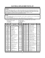
Страница 16: ...S 3210V00165B 502 AZ780022 FRAME CHASSIS HIPS 40AF DN 44SZ60D SMPS 3210V00191A 503 AZ780023 BRACKET ASSEMBLY REAR AV RU 44SZ83D NON BOARD TERMINAL 4811V00125G 520 AZ680001 PCB ASSEMBLY MAIN MB 042G M I FOR RU 44SZ83D TOSHIBA OEM 6871VMMT51A 530 AZ680002 PCB ASSEMBLY POWER SMPS MB042G M I FOR RU 44SZ83D TOSHIBA OEM 6871VPMA84A 540 AZ680003 PCB ASSEMBLY SUB TUNER MB 042G M I FOR RU 44SZ83D TOSHIBA O...

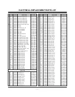
Страница 17: ... TO220 ST 5V 0IMCRKE018A IC300 AZ681022 VPC3230D C5 80P VIDEO 0IIT323000E PROCESSOR IC301 AZ681023 M74HC123RM13TR 16P 0ISTLSSG009A IC302 AZ681024 XC95144XL 10TQ100C 3 3V 0IMCRXL003A IC304 AZ681025 P82B715T 8SOP 0IPH827150A IC305 AZ681026 AT24C02N 10SI 2 7 8P 0IMMRAL014B IC306 AZ681027 AD9883AKST 110 80P DIGITAL 0IMCRAD002A BOARD IC307 AZ681028 SIL 169CT100 100P 0IMCRS5003A IC4 AZ681029 KA75420ZTA ...

Страница 18: ...AZ580002 CHIP 2SC3875S ALY KEC 0TR387500AA Q203 AZ580002 CHIP 2SC3875S ALY KEC 0TR387500AA Q204 AZ580002 CHIP 2SC3875S ALY KEC 0TR387500AA LOCA NO PART NO DESCRIPTION REFERENCE NO Q205 AZ580002 CHIP 2SC3875S ALY KEC 0TR387500AA Q206 AZ580006 KRA102S SOT23 CHIP TR 0TR102008AA Q207 AZ580002 CHIP 2SC3875S ALY KEC 0TR387500AA Q208 AZ580002 CHIP 2SC3875S ALY KEC 0TR387500AA Q209 AZ580002 CHIP 2SC3875S ...

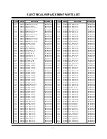
Страница 19: ...106DF618 C111 AZ180002 47UF STD 16V M 0CE476DF618 C112 AZ180008 100UF STD 16V M 0CE107DF618 LOCA NO PART NO DESCRIPTION REFERENCE NO C113 AZ180007 1UF 2012 16V 20 0CK105DF64A C115 AZ180005 10UF STD 16V M 0CE106DF618 C116 AZ180009 47UF KME 50V M 0CE476BK618 C117 AZ180002 47UF STD 16V M 0CE476DF618 C118 AZ180008 100UF STD 16V M 0CE107DF618 C120 AZ180008 100UF STD 16V M 0CE107DF618 C1200 AZ180010 10U...

Страница 20: ... 0 1UF 1608 16V 10 0CK104CF56A C610 AZ180020 0 1UF 1608 16V 10 0CK104CF56A LOCA NO PART NO DESCRIPTION REFERENCE NO C611 AZ180020 0 1UF 1608 16V 10 0CK104CF56A C612 AZ180020 0 1UF 1608 16V 10 0CK104CF56A C614 AZ180020 0 1UF 1608 16V 10 0CK104CF56A C615 AZ180020 0 1UF 1608 16V 10 0CK104CF56A C616 AZ180008 100UF STD 16V M 0CE107DF618 C616 AZ180020 0 1UF 1608 16V 10 0CK104CF56A C617 AZ180020 0 1UF 16...

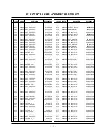
Страница 21: ...16V M 0CE106DF618 C734 AZ180014 47UF MVG 16V M 0CE476SF6DC LOCA NO PART NO DESCRIPTION REFERENCE NO C734 AZ180020 0 1UF 1608 16V 10 0CK104CF56A C735 AZ180020 0 1UF 1608 16V 10 0CK104CF56A C735 AZ180030 0 0068UF D 100V 10 0CQ6821N509 C736 AZ180005 10UF STD 16V M 0CE106DF618 C736 AZ180020 0 1UF 1608 16V 10 0CK104CF56A C737 AZ180020 0 1UF 1608 16V 10 0CK104CF56A C737 AZ180030 0 0068UF D 100V 10 0CQ68...

Страница 22: ... 35V M 0CE107DJ618 C833 AZ180020 0 1UF 1608 16V 10 0CK104CF56A LOCA NO PART NO DESCRIPTION REFERENCE NO C833 AZ180048 10P 50V D NP0 TS 0CC1000K115 C834 AZ180020 0 1UF 1608 16V 10 0CK104CF56A C834 AZ180049 0 1UF 50V Z F TR 0CK1040K945 C835 AZ180006 22UF MVG 16V 20 0CE226SF6DC C835 AZ180020 0 1UF 1608 16V 10 0CK104CF56A C836 AZ180020 0 1UF 1608 16V 10 0CK104CF56A C836 AZ180050 0 001UF D 1 6KV J 181 ...

Страница 23: ...SOCKET 6630B60F532 LOCA NO PART NO DESCRIPTION REFERENCE NO P102 AZ780008 CONNECTOR D SUB 24P 1 91MM 6630GZ00724 P102B AZ780007 CONNECTOR DIN41612 SOCKET 6630B60F532 P104 AZ780009 CONNECTOR D SUB 9PIN 2 77MM 6630VGA004A P1200B AZ780007 CONNECTOR DIN41612 SOCKET 6630B60F532 P300 AZ780008 CONNECTOR D SUB 24P 1 91MM 6630GZ00724 RESISTOR AR1001 AZ280001 22 OHM 1 16W 1608 5 0RRZVTA001D AR1002 AZ280001 ...

Страница 24: ...682002 SWITCH TACT 2LEAD 160G TA 140 313B SW6 AZ682002 SWITCH TACT 2LEAD 160G TA 140 313B SW7 AZ682002 SWITCH TACT 2LEAD 160G TA 140 313B SW701 AZ682003 SWITCH DIP 1 1437590 3 50VDC 6600DU2093V LOCA NO PART NO DESCRIPTION REFERENCE NO FILTER CRYSTAL FB851 AZ380001 FILTER EMC BFD3565R2F 125 123A FB861 AZ380001 FILTER EMC BFD3565R2F 125 123A FB871 AZ380001 FILTER EMC BFD3565R2F 125 123A FB882 AZ3800...

Страница 25: ...BMS400 25V 200MA 6200QJ3001A T603 AZ380012 FILTER EMC BMS400 25V 200MA 6200QJ3001A T604 AZ380012 FILTER EMC BMS400 25V 200MA 6200QJ3001A X1 AZ380013 RESONATOR CRYSTAL HC49U 156 A01P 8 000MHZ X100 AZ380014 RESONATOR CRYSTAL HC49 SM 6212AB2015D 16MHZ X102 AZ380015 RESONATOR CRYSTAL SX 1SMD 6202VDT002E 20250000HZ X1202 AZ380016 RESONATOR CRYSTAL HC49U 156 A01E 4 000MHZ X1203 AZ380017 RESONATOR CRYSTA...

Страница 26: ...TOSHIBA CORPORATION 1 1 SHIBAURA 1 CHOME MINATO KU TOKYO 105 8001 JAPAN ...

Отзывы: