
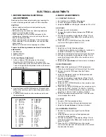


ELECTRICAL ADJUSTMENTS
2-15: SUB TINT/SUB COLOR
1.
2.
3.
4.
5.
6.
7.
8.
9.
10.
11.
12.
13.
14.
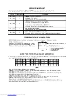
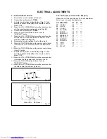
2-16: Confirmation of Fixed Value (Step No.)
Please check if the fixed values of the each adjustment
items are set correctly referring below.
NO.
05
06
08
10
21
22
23
24
25
26
27
28
29
FUNCTION
V. POSI
H. SIZE
V. CENT
VS. CORR
SHARP
RGB CONT
PARABOLA
TRAPEZIU
COR TOP
COR BTM
V EHT
H EHT
FM. LVL
RF
00
00
32
12
30
25
00
00
00
00
00
00
01
CS
---
---
---
---
30
---
---
---
---
---
---
---
---
AV
---
---
---
---
30
---
---
---
---
---
---
---
---
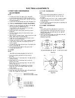
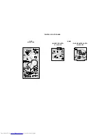
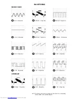
Receive the color bar pattern. (RF Input)
Connect the oscilloscope to TP806.
Activate the adjustment mode display of Fig. 1-1 and
press the channel button (20) on the remote control to
select "TINT".
Press the VOL. UP/DOWN button on the remote control
until the waveform becomes as shown in Fig. 2-2.
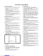
Connect the oscilloscope to TP804.
Press the CH DOWN button 3 times to set to
"SUBCONT" mode.
Press the VOL. UP/DOWN button on the remote control
until the red color level is adjusted to 105
±
5% of the
white level. (Refer to Fig. 2-3)
Receive the color bar pattern. (Audio Video Input)
Press the TV/VIDEO button on the remote control to set
to the AV mode. Then perform the above adjustments
2~7.
Press the TV/VIDEO button on the remote control to set
to the CS mode.
Activate the adjustment mode display of Fig. 1-1 and
press the channel button (20) on the remote control to
select "TINT".
Press the VOL. UP/DOWN button on the remote control
to increase the step numbers by 6 steps to the AV.
Press the CH DOWN button 3 times to set to
"SUBCONT" mode.
Press the VOL. UP/DOWN button on the remote control
to set the same step number as the AV.
Fig. 2-2
Fig. 2-3
White 100%
RED Level


