ELECTRICAL ADJUSTMENTS
2-7: VERTICAL LINEALITY
NOTE: Adjust after performing adjustments in section 2-6.
1.
2.
3.
4.
Receive the center cross signal from the Pattern
Generator.
Using the remote control, set the brightness and
contrast to normal position.
Activate the adjustment mode display of Fig. 1-1 and
press the channel button (09) on the remote control to
select "V. LIN".
Press the VOL. UP/DOWN button on the remote
control until the upside and downside screen size of the
horizontal line becomes the same.
2-8: VERTICAL POSITION
NOTE: Adjust after performing adjustments in section 2-7.
1.
2.
Receive the center cross signal from the Pattern
Generator.
Adjust the VR401 until the horizontal line becomes fit to
the notch of the shadow mask.
2-9: VERTICAL SIZE
NOTE: Adjust after performing adjustments in section 2-8.
1.
2.
3.
4.
Receive the crosshatch signal from the Pattern
Generator.
Activate the adjustment mode display of Fig. 1-1 and
press the channel button (07) on the remote control to
select "V. SIZE".
Press the VOL. UP/DOWN button on the remote
control until the rectangle on the center of the screen
becomes square.
Receive a broadcast and check if the picture is normal.
B
A
TV
00 OSD 15
Fig. 2-1
2-10: OSD HORIZONTAL
1.
2.
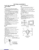
Activate the adjustment mode display of Fig. 1-1.
Press the VOL. UP/DOWN button on the remote control
until the difference of A and B becomes minimum.
(Refer to Fig. 2-1)
2-11: LEVEL
1.
2.
3.
4.
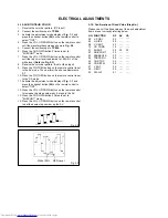
Receive the VHF HIGH (70dB).
Connect the AC voltmeter to TP901.
Activate the adjustment mode display of Fig. 1-1 and
press the channel button (30) on the remote control to
select "LEVEL".
Press the VOL. UP/DOWN button on the remote
control until the AC voltmeter is 75
±
2mV.
2-12: SEPARATION 1, 2
Receive the stereo signal (L=2KHz, R=400Hz).
Connect the AC voltmeter to AUDIO OUT JACK though
stereo filter (L=400Hz, R=2KHz).
Activate the adjustment mode display of Fig. 1-1 and
press the channel button (31) on the remote control to
select "SEP1".
Press the VOL. UP/DOWN button on the remote control
until the output of L-CH and R-CH become minimum.
Press the CH UP button once the set to "SEP2" mode.
Press the VOL. UP/DOWN button on the remote control
until the output of L-CH and R-CH become minimum.
Press the CH DOWN button once the set to "SEP1"
mode.
Repeat step 4 to step 7 several times.
The output difference of the between with Filter and
without Filter should be more than 25dB for both L and
R.
1.
2.
3.
4.
5.
6.
7.
8.
2-13: BRIGHTNESS
1.
2.
3.
4.
5.
6.
Activate the adjustment mode display of Fig. 1-1 and
press the channel button (16) on the remote control to
select "BRI".
Press the VOL. UP/DOWN button on the remote control
until the brightness step No. becomes "92"
Press the TV/VIDEO button on the remote control to set
to the AV mode. Then perform the above adjustments
1~2.
Press the TV/VIDEO button on the remote control to set
to the CS mode.
Activate the adjustment mode display of Fig. 1-1 and
press the channel button (16) on the remote control to
select "BRI".
Press the VOL. UP/DOWN button on the remote control
until the brightness step No. becomes "90"
2-14: UNI-COLOR
1.
2.
3.
4.
5.
6.
7.
8.
Activate the adjustment mode display of Fig. 1-1 and
press the channel button (18) on the remote control to
select "UNI COL".
Press the VOL. UP/DOWN button on the remote control
until the contrast step No. becomes "54"
Press the TV/VIDEO button on the remote control to set
to the AV mode.
Activate the adjustment mode display of Fig. 1-1 and
press the channel button (18) on the remote control to
select "UNI COL".
Press the VOL. UP/DOWN button on the remote control
until the contrast step No. becomes "58"
Press the TV/VIDEO button on the remote control to set
to the CS mode.
Activate the adjustment mode display of Fig. 1-1 and
press the channel button (18) on the remote control to
select "UNI COL".
Press the VOL. UP/DOWN button on the remote control
until the contrast step No. becomes "60"


