– 19 –
GENERAL ADJUSTMENTS
SPECIFIC INFORMATIONS
CALL
–/--
1
4
7
2
5
8
0
3
6
9
MENU
MENU
CH
VIDEO AUDIO
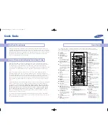
LOCATION OF CONTROLS
Front
Power switch
Remote sensor
Power Indicator
Channel select
Volume down/up
VIDEO input terminal
Audio inpuit terminal
Earphone jack
MENU
TV/VIDEO Select
Digit Select
Menu open
mute
Power ON/OFF
Direct Select
TV/VIDOE Select
Volume down/up
Level down/up
Picture control
Menu Select
on-screen on/off
Position down/up
Level down/up
Remote control