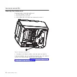
2. Install the four lower rollers:
a. Orient the roller with the large gap to the left.
b. Insert the opposite end of the roller into the mounting hole on the right side
of the printer unit frame.
c. Bend the left side of the roller slightly and insert it into the mounting hole.
d. Repeat steps 2a through 2c for each of the remaining rollers.
3. Install the upper roller:
a. Align one end of the roller with a mounting hole.
b. Press the two sides of the frame apart and insert the opposite end of the
roller into the mounting hole.
4. If necessary, replace the paper door assembly and lift springs (see “Removing
the cutter motor and paper door assembly” on page 62 for information).
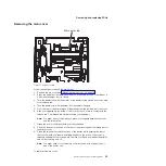
Removing the low-paper sensor
Follow these steps to remove the low-paper sensor:
1. Follow the steps in “Removing the logic card” on page 60 to access the
low-paper sensor cable connector.
Note:
Do not disconnect any cables other than the low-paper sensor cable
(three-wire connector) from the logic card.
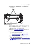
2. Remove the low-paper sensor cable from its cable guides on the left side of the
unit and slide it out from under the paper basket.
B
A
Figure 26. Place Holder for Future Artwork
Removing and replacing FRUs
66
SureMark Hardware Service
Содержание 1NA
Страница 2: ......
Страница 8: ...vi SureMark Hardware Service ...
Страница 10: ...viii SureMark Hardware Service ...
Страница 12: ...x SureMark Hardware Service ...
Страница 16: ...xiv SureMark Hardware Service ...
Страница 18: ...xvi SureMark Hardware Service ...
Страница 46: ...28 SureMark Hardware Service ...
Страница 56: ...38 SureMark Hardware Service ...
Страница 88: ...70 SureMark Hardware Service ...
Страница 90: ...Assembly 1 Models 1NR 1NA and 1ND 1 2 3 4 5 7 6 72 SureMark Hardware Service ...
Страница 92: ...Assembly 1 continued 74 SureMark Hardware Service ...
Страница 108: ...90 SureMark Hardware Service ...
Страница 109: ......
Страница 110: ...G362 0565 05 ...


