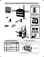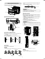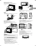
A
B
C
Toshiba 1112150201 (EN)
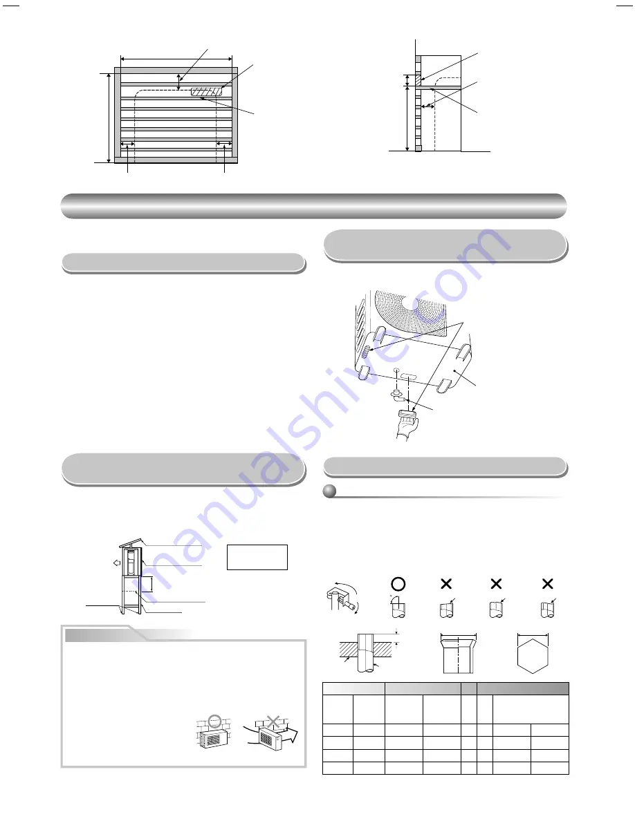
500
140
(Side view)
Partition board
20 to 30
Opening for receiver
(Front view)
800 or more
670 or more
Partition board
Opening for receiver
50 or more
50 or more
70 or more
OUTDOOR UNIT
OUTDOOR UNIT
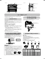
Installation Place
•
A place which provides enough spaces around the outdoor unit as shown
in the diagram.
•
A place which can bear the weight of the outdoor unit and does not allow
an increase in noise level and vibration.
•
A place where the operation noise and discharged air do not disturb your
neighbors.
•
A place which is not exposed to a strong wind.
•
A place free of a leakage of combustible gases.
•
A place which does not block a passage.
•
When the outdoor unit is to be installed in an elevated position, be sure to
secure its feet.
•
This air conditioner accepts a connection piping length from 2 m to 20 m.
•
There is no need to add refrigerant as long as the length of the
connection piping is 15 m or less.
•
You will need to add 20 g of refrigerant per meter of added connection
piping for installation requiring connection piping to be between 16 m to
20
m.
•
An allowable height level is up to 10 m.
•
A place where the drain water does not cause any problems.
CAUTION
1. Install the outdoor unit in a location where there are no obstructions
near its air intake or air outlet.
2. When the outdoor unit is installed in a place that is always exposed to
strong winds like on the coast or on a high story of a building, secure
the normal fan operation using a duct or a wind shield.
3. Especially in windy areas, install the unit to prevent the admission of
wind.
4. Installation in the following places may result in trouble.
Do not install the unit in such places.
•
A place full of machine oil.
•
A saline-place such as the coast.
•
A place full of sulfi de gas.
•
A place where high-frequency
waves are likely to be generated,
such as from audio equipment, welders, and medical equipment.
Strong
wind
Snow protection plate
Snow protection hood
At least 50 cm
Snow accumulation line
Holding frame
Front
Anchor bolts
Install at least 50 cm
above the snow
accumulation line.
•
Do not use the supplied drain nipple for draining water. Drain the water from
all the drain holes directly.
•
To protect the outdoor unit from snow accumulation, install a holding frame,
and attach a snow protection hood and plate.
* Do not use a double-stacked design.
Precautions about Installation in Regions
with Snowfall and Cold Temperatures
•
When using a multi-system outdoor unit refer to the installation manual
provided with the model concerned.
Refrigerant Piping Connection
Flaring
1. Cut the pipe with a pipe cutter.
2. Deburr the inside of the pipe at its end.
Take steps to ensure that the removed burrs will not enter the pipe.
3. Remove the fl are nuts provided with the indoor and outdoor units, and
insert them into the pipe.
4. Flare the pipe.
The projection margin of the pipe must be checked.
5. Check that the fl are has the appropriate shape.
90
Obliquity
Roughness
Warp
Pipe
Die
•
If it is necessary to drain off the water from the outdoor unit, install two
water-proofi ng rubber caps and a drain nipple.
Draining off the Water
from the Outdoor Unit
Pipe
A
B
Flare Nut
Outside
diameter
Thickness
Rigid
(clutch type)
R410A tool
Imperial
(wing nut
type)
R410A tool
C
Tighten torque
mm
mm
mm
mm
mm
mm
N·m
kgf·m
6.35
0.8
0 to 0.5
1.5 to 2.0
9.1
17
14 to 18
1.4 to 1.8
9.52
0.8
0 to 0.5
1.5 to 2.0
13.2
22
33 to 42
3.3 to 4.2
12.7
0.8
0 to 0.5
2.0 to 2.5
16.6
26
50 to 62
5.0 to 6.2
Water-proof rubber caps
(supplied with the outdoor unit)
Drain nipple
Base plate
7
Содержание 18UFV-E1
Страница 13: ...1112150201 1 ...

