26
DAA03564
B
Copyright © 2022 Toshiba Teli Corporation, All Rights Reserved.
https://www.toshiba-teli.co.jp/en/
6.5
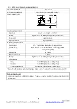
GPIO Input / Output signal specification
I/O Connector Pin No.
1 Pin : Line2
GPIO signal (LineMode)
Input / Output (factory setting : Output*)
Input / Output circuit
Inside
DC5.0V
10k
Ω
1
3
IOLineModeAll
Input signal specification
Input level
Low: 0 to 0.5V, High: 4.0 to 5.0V
Polarity
High active / Low active (factory setting : Low active)
Pulse width
50μs (minimum)
Input impedance
High impedance
Output signal specification
Output signal
(LineSource)
Off, Timer0Active, UserOutput, ExposureActive,
FrameActive, FrameTransferActive, FrameTriggerWait
(factory setting : Off)
Output level
5V CMOS
Maximum Current
+/-32mA
Polarity
High active / Low active (factory setting : Low active)
Timer0Active
Delay
0 to 2000000
μs (factory setting : 0μs)
Duration
0 to 2000000
μs (factory setting : 0μs)
TimerTriggerSource
Line0Active, ExposureStart, FrameTrigger
* Even if LineMode is set as Output, the input signal to Line2 is valid when LineSource is set as Off.
Note on Input Level:
- Line0 and Line2 have a different input level. Please use input level within the voltage described in this
specification.

