Toro Z595-D Z Master Скачать руководство пользователя страница 35

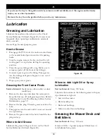
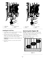
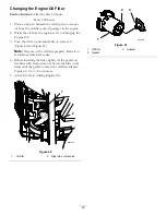
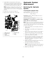
Changing the Engine Oil Filter

Service Interval:

After the first 50 hours

Every 200 hours

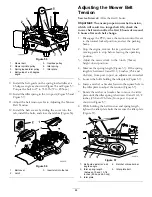
1. Place a drip pan beneath the oil drip tray to receive

oil from the oil filter and oil passages in the engine.

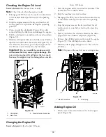
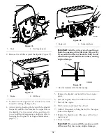
2. Drain the oil from the engine; refer to Changing the

Engine Oil.

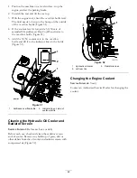
3. Turn the filter counterclockwise to remove it

(Figure 40 and Figure 41).

Note:

Dispose of the oil filter properly. Recycle in

accordance with local codes.

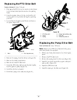
4. Before installing the filter, lightly oil the gasket on

the filter with fresh, clean oil. Screw the filter on by
hand until the gasket contacts the oil filter adapter.
Tighten 1/2 to 3/4 turn more.

5. Add oil; refer to Adding Engine Oil.

1

2

G000969

Figure 40

1.

Oil filter

2.

Right side of machine

G001056

1

2

3

Figure 41

1.

Oil filter

3.

Adapter

2.

Gasket

35

Содержание Z595-D Z Master

Страница 1: ...Form No 3358 682 Rev A Z595 D Z Master with a 72in TURBO FORCE Side Discharge Mower Model No 74274 Serial No 270000001 and Up G001093 Register at www Toro com Original Instructions EN ...

Страница 2: ...ding a dealer or to register your product Whenever you need service genuine Toro parts or additional information contact an Authorized Service Dealer or Toro Customer Service and have the model and serial numbers of your product ready Figure 1 identifies the location of the model and serial numbers on the product Write the numbers in the space provided G000935 1 Figure 1 1 Model and serial number ...

Страница 3: ... Electrical System Maintenance 36 Servicing the Battery 36 Servicing the Fuses 38 Drive System Maintenance 39 Adjusting the Tracking 39 Checking the Tire Pressure 39 Checking the Wheel Hub Slotted Nut 40 Adjusting the Caster Pivot Bearing 40 Servicing the Gear Box 40 Cooling System Maintenance 41 Servicing the Cooling System 41 Brake Maintenance 43 Adjusting the Parking Brake 43 Belt Maintenance 4...

Страница 4: ...area where the equipment is to be used and remove all objects such as rocks toys and wire which can be thrown by the machine Use extra care when handling diesel and other fuels They are flammable and vapors are explosive Use only an approved container Never refuel or drain the machine indoors Never remove fuel cap or add fuel with engine running Allow engine to cool before refueling Do not smoke C...

Страница 5: ...an be released quickly in the event of an emergency Be aware there is no rollover protection when the roll bar is down Check the area to be mowed and never fold the ROPS in areas where there are slopes drop offs or water Lower the rollbar only when absolutely necessary Do not wear the seat belt with the roll bar folded down Check carefully for overhead clearances i e branches doorways electrical w...

Страница 6: ...ld along appropriate line Align this edge with a vertical surface Tree Building Fence post pole etc Example Compare slope with folded edge TH IS IS A 5 SL O PE T H I S I S A 1 5 S L O P E T H IS IS A 1 0 S L O P E 6 ...

Страница 7: ...ructions are easily visible to the operator and are located near any area of potential danger Replace any decal that is damaged or lost 1 403005 1 523552 1 643253 54 9220 58 6520 1 Grease 66 1340 65 2690 68 8340 98 4387 1 Warning wear hearing protection 7 ...

Страница 8: ...98 5954 103 1636 105 7798 107 1613 107 1857 107 1860 107 1861 8 ...

Страница 9: ...107 1864 107 2102 107 2112 107 2114 107 2449 108 5955 108 5957 9 ...

Страница 10: ...ming maintenance 110 3852 1 Remove the ignition key and read the instructions before servicing or performing maintenance 2 Continuous tone signals the user that engine is overheating 110 3853 1 Cutting dismemberment hazard fan and entanglement hazard belt 2 Remove the ignition key and read the instructions before servicing or performing maintenance 10 ...

Страница 11: ...Manufacturer s Mark 1 Indicates the blade is identified as a part from the original machine manufacturer 110 0806 110 3842 112 8319 106 7492 11 ...

Страница 12: ...ion on charging the battery contains lead do not discard 2 Read the Operator s Manual 112 2389 1 Push to engage 6 Engine start 2 Engine preheat 7 Fast 3 Read the Operator s Manual 8 Continuous variable setting 4 Engine stop 9 Slow 5 Engine run 10 PTO Power take off 12 ...

Страница 13: ... plug switch 8 Audible alarm 4 Glow plug light 9 Fuel selector valve 5 Engine Temperature light Hour Meter The hour meter records the number of hours the engine has operated It operates when the engine is running Use these times for scheduling regular maintenance Figure 4 Glow Plug Light The glow plug indicator light turns on when the glow plug button is engaged Figure 4 Glow Plug Switch This swit...

Страница 14: ...ensure fuel freshness Use summer grade diesel fuel No 2 D at temperatures above 20 F 7 C and winter grade diesel fuel No 1 D or No 1 D 2 D blend below 20 F 7 C Use of winter grade diesel fuel at lower temperatures provides lower flash point and pour point characteristics therefore easing startability and lessening chances of chemical separation of the fuel due to lower temperatures wax appearance ...

Страница 15: ...enser nozzle If a fuel dispenser nozzle must be used keep the nozzle in contact with the rim of the fuel tank or container opening at all times until fueling is complete Filling the Fuel Tank 1 Shut the engine off and set the parking brake 2 Clean around each fuel tank cap and remove the cap Add fuel to both fuel tanks until the level is 1 4 to 1 2 inch 6 to 13 mm below the bottom of the filler ne...

Страница 16: ...ad clearances i e branches doorways electrical wires before driving under any objects and do not contact them Important Lower the roll bar only when absolutely necessary 1 Remove the hairpin cotter pins and remove the two pins Figure 7 2 Lower the the roll bar to the down position There are two down positions See Figure 6 for the positions 3 Install the two pins and secure them with the hairpin co...

Страница 17: ...s injury death or drowning There is no rollover protection when the roll bar is down Always keep the roll bar in the raised and locked position and use the seat belt Read and follow the rollover protection instructions and warnings To avoid loss of control and possibility of rollover Do not operate near drop offs or near water Do not operate on slopes greater than 15 degrees Reduce speed and use e...

Страница 18: ...onal injury or property damage Do not park on slopes unless wheels are chocked or blocked Releasing the Parking Brake Push forward and down on the parking brake lever to release the parking brake Figure 10 The parking brake is disengaged and the lever will rest against the brake stop G000964 1 2 3 Figure 10 1 Parking brake ON 3 Brake Stop 2 Parking brake OFF Starting and Stopping the Engine Starti...

Страница 19: ...tarting the engine for the first time after the fuel system has been completely without fuel G001063 2 3 4 1 Figure 12 1 Ignition switch 3 Run 2 Off 4 Start G001062 1 2 Figure 13 1 Throttle fast 2 Throttle slow Starting the Engine in Cold Weather Below 23 F or 5 C Use the correct engine oil for the starting temperature Refer to Servicing the Engine Oil in Engine Maintenance page 31 1 Start the eng...

Страница 20: ...ractor while it is unattended Always remove the ignition key and set the parking brake when leaving the machine unattended even if just for a few minutes Operating the Power Take Off PTO The power take off PTO switch starts and stops the mower blades and any powered attachments Engaging the PTO 1 If the engine is cold allow the engine to warm up 5 to 10 minutes before engaging the PTO 2 While seat...

Страница 21: ... Now start the engine While the engine is running center either motion control and move forward or reverse the engine should stop Repeat for other motion control 5 Sitting on the seat disengage the parking brake move the PTO switch to off and move the motion control levers to neutral lock position Try starting the engine the engine should not crank Driving Forward or Backward The throttle control ...

Страница 22: ...may be injured if they move or attempt to operate the tractor while it is unattended Always remove the ignition key and set the parking brake when leaving the machine unattended even if just for a few minutes Adjusting the Height of Cut The height of cut is adjusted from 1 1 2 to 5 inch 38 to 127 mm in 1 4 inch 6 mm increments by relocating the clevis pin into different hole locations 1 Raise the ...

Страница 23: ...r 3 Flange Nut 2 Bushing 4 Bolt G000944 1 2 3 4 5 Figure 19 1 Anti scalp roller 4 Flange Nut 2 Spacer 5 Bolt 3 Bushing Adjusting the Flow Baffle The mower discharge flow can be adjusted for different types of mowing conditions Position the cam locks and baffle to give the best quality of cut 1 Disengage the PTO move the motion control levers to the neutral locked position and set the parking brake...

Страница 24: ... mowing conditions Use in dry conditions For smaller grass clippings Propels grass clippings farther away from the mower G000946 Figure 21 Position B Use this position when bagging G000947 Figure 22 Position C This is the full open position The suggested use for this position is as follows Use in tall dense grass mowing conditions Use in wet conditions Lowers the engine power consumption Allows in...

Страница 25: ... neutral locked position and apply parking brake Remove the key 2 Rotate the by pass valves counterclockwise 1 turn to push This allows hydraulic fluid to by pass the pump enabling the wheels to turn Figure 26 Important Do not rotate by pass valves more than 1 turn This prevents valves from coming out of the body and causing fluid to run out 3 Disengage parking brake before pushing Changing to Mac...

Страница 26: ...ommended instead of individual ramps for each side of the unit Figure 27 The lower rear section of the tractor frame extends back between the rear wheels and serves as a stop for tipping backward Having a full width ramp provides a surface for the frame members to contact if the unit starts to tip backward If it is not possible to use one full width ramp use enough individual ramps to simulate a f...

Страница 27: ...fferent rates at different times So to maintain the same cutting height which is a good practice mow more often in early spring As the grass growth rate slows in mid summer mow less frequently If you cannot mow for an extended period first mow at a high cutting height then mow again two days later at a lower height setting Cutting Speed To improve cut quality use a slower ground speed in certain c...

Страница 28: ...isease Check the cutter blades daily for sharpness and for any wear or damage File down any nicks and sharpen the blades as necessary If a blade is damaged or worn replace it immediately with a genuine TORO replacement blade 28 ...

Страница 29: ...raulic fluid Every 50 hours Check the tire pressure or monthly which ever comes first Check the PTO drive belt Check the pump drive belt Check the alternator belt Every 100 hours Change the engine oil Check the gear box oil level Check the engine cooling system hoses Inspect the belts for cracks and wear Check the hydraulic hoses Every 150 hours Lubricate the machine with light oil Every 200 hours...

Страница 30: ... to ooze out of the bearings 5 Wipe up any excess grease Greasing the Front Caster Pivots Service Interval Yearly more often in dirty or dusty conditions 1 Remove the dust cap and adjust the caster pivots Keep the dust cap off until greasing is done Refer to Adjusting the Caster Pivot Bearing in Drive System Maintenance page 39 2 Remove the hex plug Thread a grease zerk into the hole 3 Pump grease...

Страница 31: ...ly dusty or sandy Removing the Air Filter Service Interval Every 250 hours more often in dirty or dusty conditions 1 Disengage the PTO move the motion control levers to the neutral locked position and set the parking brake 2 Stop the engine remove the key and wait for all moving parts to stop before leaving the operating position 3 Release the latches on the air cleaner and pull the air cleaner co...

Страница 32: ...t press on the soft inside area of the filter 3 Install the air cleaner cover and secure the latches Figure 32 G001048 1 2 3 4 Figure 32 1 Air filter body 3 Air cleaner cover 2 Air filter 4 Latches Servicing the Engine Oil Oil Type High quality detergent oil classified API Service CD or higher for diesel engines Do not use special additives with recommended oils Crankcase Capacity 3 9 quarts 3 7 l...

Страница 33: ...with oil below the low mark because the engine may be damaged as a result G001057 1 2 3 Figure 34 1 Oil dipstick 3 Rear left side of machine 2 Metal end Changing the Engine Oil Service Interval After the first 50 hours Every 100 hours 1 Start the engine and let it run for five minutes This warms the oil so it drains better 2 Park the machine on a level surface 3 Disengage the PTO move the motion c...

Страница 34: ...ngine oil 2 Funnel and hose Important Add the oil very slowly and do not block the opening of the filler hole Figure 39 If you add oil too fast or block the hole the oil could back up and foul the air intakes causing engine damage 1 G000955 Figure 39 1 Note the clearance left in the filler opening 5 Replace the dipstick and install the front engine panel 6 Start the engine and run it at idle for 5...

Страница 35: ... counterclockwise to remove it Figure 40 and Figure 41 Note Dispose of the oil filter properly Recycle in accordance with local codes 4 Before installing the filter lightly oil the gasket on the filter with fresh clean oil Screw the filter on by hand until the gasket contacts the oil filter adapter Tighten 1 2 to 3 4 turn more 5 Add oil refer to Adding Engine Oil 1 2 G000969 Figure 40 1 Oil filter...

Страница 36: ... system Electrical System Maintenance Servicing the Battery Warning CALIFORNIA Proposition 65 Warning Battery posts terminals and related accessories contain lead and lead compounds chemicals known to the State of California to cause cancer and reproductive harm Wash hands after handling Battery electrolyte contains sulfuric acid which is a deadly poison and causes severe burns Do not drink electr...

Страница 37: ... 3 Red cable 2 Positive Battery Post 4 Black cable 6 Remove both wing nuts 1 4 inch securing the battery clamp Figure 43 7 Remove the two bolts holding the hydraulic tank in place Figure 43 8 Slide the hydraulic tank away from the battery 9 Remove the battery 1 2 3 4 5 G001050 Figure 43 1 Battery 4 Wing nut 2 Hydraulic tank 5 Right side fuel tank 3 Bolts Installing the Battery 1 Position battery i...

Страница 38: ...Installing the Battery Note Do not run the machine with the battery disconnected electrical damage may occur G000960 1 2 3 4 Figure 44 1 Positive Battery Post 3 Red Charger Lead 2 Negative Battery Post 4 Black Charger Lead Servicing the Fuses The electrical system is protected by fuses It requires no maintenance however if a fuse blows check component circuit for malfunction or short Fuse Ignition...

Страница 39: ...sides of the machine from the normal operating position 4 To make the machine go right turn the knob towards the rightside of the machine Refer to Figure 46 5 To make the machine go left turn the knob towards the leftside of the machine Refer to Figure 46 6 Repeat adjustment until the tracking is correct G001070 2 3 1 4 5 Figure 46 1 Tracking knob 4 Turn this way to track right 2 Hydraulic tank 5 ...

Страница 40: ...mes first 1 Disengage the PTO move the motion control levers to the neutral locked position and set the parking brake 2 Stop the engine remove the key and wait for all moving parts to stop before leaving the operating position 3 Remove the dust cap from caster and tighten lock nut Figure 49 4 Tighten the locknut until the spring washers are flat and then back off a 1 4 turn to properly set the pre...

Страница 41: ...e removing the radiator cap Do not touch radiator and surrounding parts that are hot Rotating shaft and fan can cause personal injury Do not operate the machine without the covers in place Keep fingers hands and clothing clear of rotating fan and drive shaft Shut off the engine and remove the ignition key before performing maintenance Swallowing engine coolant can cause poisoning Do not swallow en...

Страница 42: ...ottle and fill it to the indicator line on the bottle Figure 51 G001103 G001103 1 2 1 Figure 51 1 Antifreeze overflow bottle 2 Indicator line on side of overflow bottle Cleaning the Hydraulic Oil Cooler and Radiator Screen Service Interval Before each use or daily Before each use check and clean the radiator screen and oil cooler Remove any build up of grass dirt or other debris from the oil coole...

Страница 43: ...e Interval Every 100 hours Check the belts for squealing when the belt is rotating blades slipping when cutting grass frayed belt edges burn marks and cracks are signs of a worn mower belt Replace the mower belt if any of these conditions are evident Replacing the Mower Belt Squealing when the belt is rotating blades slipping when cutting grass frayed belt edges burn marks and cracks are signs of ...

Страница 44: ...hange 1 Disengage the PTO move the motion control levers to the neutral locked position and set the parking brake 2 Stop the engine remove the key and wait for all moving parts to stop before leaving the operating position 3 Adjust the mower deck to the 3 inch 76mm height of cut position 4 Measure the spring length Figure 57 If the spring length is between 10 and 10 1 4 inches 25 4 and 26 0 cm fro...

Страница 45: ...e PTO drive belt around the clutch pulley and the gearbox pulley Figure 59 8 Intall the clutch stop bracket 9 Install the spring to the idler arm Figure 59 G001157 1 2 3 4 5 6 Figure 59 1 PTO Drive belt 4 Spring loaded idler pulley 2 Clutch 5 Gear box 3 Spring 6 Clutch stop bracket Replacing the Pump Drive Belt Service Interval Every 50 hours Note Remove the PTO drive belt first if the pump drive ...

Страница 46: ...e machine Figure 61 G001295 1 2 3 2 Figure 61 1 Oil cooler shield 3 Engine straps 2 Bolts 5 Remove the 4 bolts holding the oil cooler and position the oil cooler to the side Figure 62 6 Remove the 2 bolts holding the fan and fan plate to the machine Figure 62 G001296 1 2 3 4 Figure 62 1 Oil cooler 3 Fan plate 2 Fan 4 Alternator belt 7 Loosen the bottom bolt and remove the upper bolt holding the al...

Страница 47: ...e Neutral Position If motion control levers do not align or move easily into the console notch adjustment is required Adjust each lever spring and rod separately Note Motion control levers must be installed correctly See Installing the Motion Control Levers in the set up instructions 1 Disengage the PTO move the motion control levers to the neutral locked position and set the parking brake 2 Stop ...

Страница 48: ... l Important Use oil specified or equivalent Other fluids could cause system damage Note There are two ways of checking the hydraulic oil One is when the oil is warm and one is when the oil is cold The baffle inside the tank has two levels depending if the oil is warm or cold 1 Position the machine on a level surface and set the parking brake 2 Clean the area around filler neck of hydraulic tank F...

Страница 49: ... summer filter above 32 F 0 C Use winter filter below 32 F 0 C 1 Disengage the PTO move the motion control levers to the neutral locked position and set the parking brake 2 Stop the engine remove the key and wait for all moving parts to stop before leaving the operating position Important Do not substitute automotive oil filter or severe hydraulic system damage may result 3 Place drain pan under f...

Страница 50: ...el Checking the Hydraulic Hoses Service Interval Every 100 hours After every 100 operating hours check the hydraulic hoses for leaks loose fittings kinked lines loose mounting supports wear weather and chemical deterioration Make necessary repairs before operating Note Keep areas around the hydraulic system clean from grass and debris build up Hydraulic fluid escaping under pressure can penetrate ...

Страница 51: ...ontrol lever forward and reverse then back to neutral The wheel must stop turning or slightly creep in reverse 4 Open the throttle to fast Make sure wheel remains stopped or slightly creeps in reverse adjust if necessary G001070 2 3 1 4 5 Figure 70 1 Tracking knob 4 Turn this way to track right 2 Hydraulic tank 5 Turn this way to track left 3 Hydraulic pumps Setting the Left hand Hydraulic Pump Ne...

Страница 52: ...nd set the parking brake 3 Stop the engine remove the key and wait for all moving parts to stop before leaving the operating position 4 Check tire pressure of all four tires If needed adjust to 13 psi 90 kPa 5 Lower the mower to the 3 inch 76 mm height of cut position 6 Inspect the four chains The chains need to have tension If one rear chain is loose lower loosen the front support arm on the same...

Страница 53: ...he cutting edge of the blade tip Figure 74 A B 1 2 G001041 Figure 74 1 Measure here from blade to hard surface 2 Measure at A and B 3 Record this measurement 4 Measure the right blade at the B location from a level surface to the cutting edge of the blade tip Figure 74 5 Record this measurement 6 The mower blade should be a 1 4 to 3 8 inch 6 to 10 mm lower at position A than at position B Figure 7...

Страница 54: ...to keep extra blades on hand A worn or damaged blade can break and a piece of the blade could be thrown into the operator s or bystander s area resulting in serious personal injury or death Inspect the blade periodically for wear or damage Replace a worn or damaged blade Inspect and check the blades every 8 hours Before Inspecting or Servicing the Blades Park the machine on a level surface disenga...

Страница 55: ...nce of the machine use genuine TORO replacement blades Replacement blades made by other manufacturers may result in non conformance with safety standards Contact with a sharp blade can cause serious injury Wear gloves or wrap sharp edges of the blade with a rag 1 Hold the blade end using a rag or thickly padded glove 2 Remove the blade bolt spring disk and blade from the spindle shaft Figure 80 Sh...

Страница 56: ... you install a cover plate a mulch plate or a grass chute and catcher Make sure the grass deflector is in the down position 1 Remove the locknut bolt spring and spacer holding the deflector to the pivot brackets Figure 81 Remove the damaged or worn grass deflector 2 Place the spacer and spring onto grass deflector Place the L end of spring behind deck edge Note Make sure the L end of the spring is...

Страница 57: ...refer to Servicing the Brake in Brake Maintenance page 43 4 Service the air cleaner refer to Servicing the Air Cleaner in Engine Maintenance page 31 5 Grease the machine refer to Greasing and Lubrication in Lubrication page 30 6 Change the crankcase oil refer to Servicing the Engine Oil in Engine Maintenance page 31 7 Check the tire pressure refer to Checking the Tire Pressure in Drive System Main...

Страница 58: ...ws Repair or replace any part that is damaged 14 Paint all scratched or bare metal surfaces Paint is available from your Authorized Service Dealer 15 Store the machine in a clean dry garage or storage area Remove the key from the ignition switch and keep it out of reach of children or other unauthorized users Cover the machine to protect it and keep it clean 58 ...

Страница 59: ...ugged 5 Clean or replace the fuel cap 6 Dirt or water in the fuel filter 6 Replace the fuel filter Engine loses power 7 Dirt water or stale fuel is in the fuel system 7 Contact an Authorized Service Dealer 1 Engine load is excessive 1 Reduce the ground speed 2 Oil level in the crankcase is low 2 Add oil to the crankcase Engine overheats 3 Cooling fins and air passages above the engine are plugged ...

Страница 60: ...ressure Uneven cutting height 6 Blade spindle bent 6 Contact an Authorized Service Dealer 1 Drive belt is worn loose or broken 1 Check the belt tension 2 Drive belt is off pulley 2 Install drive belt and check adjusting shafts and belt guides for correct position 3 Deck belt is worn loose or broken 3 Install new deck belt 4 Deck belt is off pulley 4 Install deck pulley and check the idler pulley i...

Страница 61: ...Schematics Wire Diagram Rev A 61 ...

Страница 62: ...Notes 62 ...

Страница 63: ...cheduled for replacement as required maintenance in the written instructions must be warranted for the warranty period of two years If any such part fails during the period of warranty coverage it must be repaired or replaced by The Toro Company Any such part repaired or replaced under the warranty must be warranted for a time not less than the remaining warranty period B Any warranted part that i...

Страница 64: ...is no other express warranty except for special emission system coverage on some products This express warranty does not cover the following Cost of regular maintenance service or parts such as lters fuel lubricants tune up parts blade sharpening brake and clutch adjustments Any product or part which has been altered or misused or required replacement or repair due to normal wear accidents or lack...

Отзывы: