background image

CHASSIS

3-5

Z580/Z593/Z595 Diesel Service Manual 

3

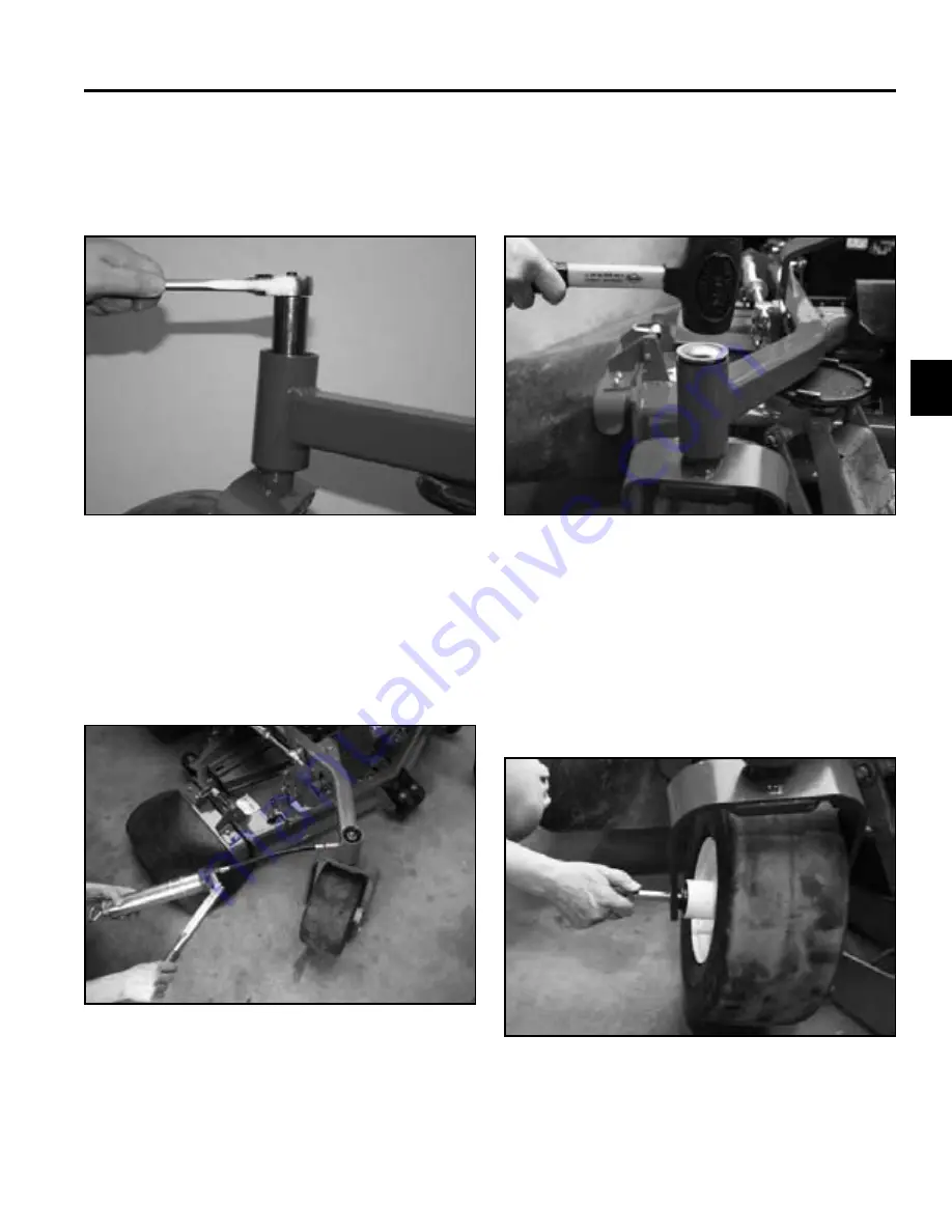
3.  Install the locknut. Tighten the locknut until the 

Belleville washers are fl at, then back the nut off 1/4 
turn to properly set the preload on the bearings (Fig. 
016).

5.  Remove the grease fi tting and install the grease 

plug.

6.  Install the dust cap onto the frame (Fig. 018).


Fig 016

 IMG_7874a


Fig 018

 IMG_7734

1.  Raise the front of the machine off the ground.

2.  Remove the wheel axle bolt and nut (Fig. 019).

4.  Remove the plug located on the side of the castor 

hub. Install a grease fi tting. Apply grease (No. 
2 general purpose lithium base or molybdenum 
grease) into the hub until it passes through the upper 
bearing. Fill the top cavity with grease (Fig. 017).


Fig 019

 IMG_7736


Fig 017

 PICT-2897

Front Wheel Removal & Bearing 
Replacement

Содержание Z580-D

Страница 1: ...LCE Products Z580 D Z593 D Z595 D Diesel Z Master Service Manual ...

Страница 2: ...m 492 4777 Electrical Troubleshooting Interactive electrical troubleshooting and wiring diagrams on DVD Form 492 9171 The Z Master 593 595 580 model years 2006 to 2008 are covered in this manual The manual may also be specified for use on later model products The hydrostatic drive system is precision machinery Maintain strict cleanliness control during all stages of service and repair Cover or cap...

Страница 3: ...THIS PAGE INTENTIONALLY LEFT BLANK ...

Страница 4: ...sembly Replacement 3 1 Castor Fork Assembly Removal 3 1 Castor Bearing Replacement 3 1 Castor Fork Assembly Installation 3 4 Front Wheel Removal Bearing Replacement 3 5 Fuel Tank Replacement 3 9 Right Side Fuel Tank Removal 3 9 Right Side Fuel Tank Installation 3 11 Left Side Fuel Tank Removal 3 14 Left Side Fuel Tank Installation 3 17 Fuel Tank Fitting Replacement 3 20 Hood Assembly Replacement 3...

Страница 5: ...r Installation 4 20 Purging the Hydraulic System 4 24 Adjusting the Control Handle Neutral Position 4 25 Setting the Hydrostatic Pump Neutral 4 27 Setting the Right Hydraulic Pump Neutral Position 4 28 Setting the Left Hydraulic Pump Neutral Position 4 28 Adjusting the Tracking 4 30 Hydraulic Flow Testing 4 31 Hydraulic Flow Testing Procedure 4 31 Traction Pump Drive Belt Replacement 4 35 Traction...

Страница 6: ... 62 Fuel Filter Service 5 63 Fuel Filter Replacement 5 64 Draining the Water Separator 5 66 Checking the Radiator Coolant 5 66 ELECTRICAL General 6 1 Engine Starting 6 1 Relays 6 1 Purpose 6 1 Location 6 1 How It Works 6 2 Testing 6 2 PTO Switch 6 3 Purpose 6 3 Location 6 3 How It Works 6 3 Testing 6 4 Ignition Switch 6 5 Purpose 6 5 Location 6 5 How It Works 6 5 Testing 6 6 Neutral Safety Switch ...

Страница 7: ...e 6 13 Location 6 13 How It Works 6 14 Testing 6 14 High Temperature Glow Plug Light Cluster 6 14 Purpose 6 14 Location 6 14 How It Works 6 15 Testing 6 15 Glow Plug Switch 6 15 Purpose 6 15 Location 6 15 How It Works 6 16 Testing 6 16 Hour Meter 6 16 Purpose 6 16 Location 6 16 How It Works 6 17 Testing 6 17 Electric PTO Clutch 6 17 Purpose 6 17 Location 6 17 How It Works 6 18 Testing 6 18 Clutch ...

Страница 8: ...on Ogura Clutch 7 40 Gearbox Assembly Replacement 7 44 Gearbox Assembly Removal 7 44 Gearbox Assembly Installation 7 49 Checking the Gearbox Oil Level 7 54 Changing Gearbox Oil 7 54 Strut Replacement 7 55 Strut Removal 7 55 Strut Installation 7 58 72 Mower Deck Belt Tension Adjustment Plate Replacement 7 61 72 Mower Deck Belt Tension Adjustment Plate Removal 7 61 72 Mower Deck Belt Tension Adjustm...

Страница 9: ...vi Z580 Z593 Z595 Diesel Service Manual TABLE OF CONTENTS THIS PAGE INTENTIONALLY LEFT BLANK ...

Страница 10: ...s which may increase in temperature during operation while the unit is running or shortly after it has been running Avoid fires and explosions Avoid spilling fuel and never smoke while working with any type of fuel or lubricant Wipe up any spilled fuel or oil immediately Never remove the fuel cap or add fuel when the engine is running Always use approved labeled containers for storing or transport...

Страница 11: ...SAFETY INFORMATION 1 2 Z580 Z593 Z595 Diesel Service Manual 1 THIS PAGE INTENTIONALLY LEFT BLANK ...

Страница 12: ... Electromagnetic 200 ft lbs 271 Nm Electromagnetic Hydraulic Pumps Tandem Hydro Gear 16cc w shock valves Hydro Gear 16cc w system relief Wheel Motors 2 Hydro Gear 18E 1 1 4 3 175cm Tapered Shaft Hydro Gear 18E 1 1 4 3 175cm Tapered Shaft Maximum Ground Speed f r 11 mph 17 7 km hr 6 3 mph 10 km hr 11 2 mph 18 km hr 6 3 mph 10 km hr Hour Meter Standard Standard Rear Drive Tires 23 x 9 5 12 52 24 x 1...

Страница 13: ...aft Bearings 1 2 54cm Steel Shaft Tapered Roller 1 2 54cm Steel Shaft Tapered Roller Blades 3 1 4 635cm Heat Treated Steel 1 4 635cm Heat Treated Steel Blade Tip Speed 18 500 ft min 5 638 8 meters min 18 500 ft min 5 638 8 meters min Belt Construction Aramid Fiber V Belt Aramid Fiber V Belt Enhanced Belt Wrap Minimizes Belt Slip Minimizes Belt Slip Discharge Chute 5 16 79cm Rubber 5 16 79cm Rubber...

Страница 14: ...Elastomeric Seat Belt Retractable Retractable Arm Rests Standard Standard Seat Suspension System Optional Optional Beverage Holder Standard Standard Folding ROPS Standard Standard Z Stand Optional Optional Deck Lift Assist Pedal Standard Standard Z593 D Pro Performance Z595 D Pro Performance Weight 52 60 1426 1470 lbs 646 8 666 8kg 60 72 1443 1484 lbs 654 5 673 1kg ROPS Height 72 182 9cm 72 182 9c...

Страница 15: ...stem Capacity 4 2 quarts 4 0 liters Wheel Motors 2 Twin Hydro Gear 18E positive displacement 1 25 3 2cm Tapered Shaft Maximum Ground Speed f r 11 mph 6 3 mph 17 7km hr 10km hr Hour Meter Standard Rear Drive Tires 24 x 12 0 12 52 23 x 9 5 12 60 72 Front Caster Tires Semi Pneumatic 13 x 6 50 6 Fuel Capacity Diesel 2 or 20 Bio Diesel 12 gallons 45 liters Specifications Z580 D Configurations Power Sys...

Страница 16: ...Treated Steel Blade Tip Speed 18 500 ft min 5 638 8 meters min Belt Construction Single Kevlar cord V Belt Cutting Height 1 1 2 5 in 25 increments 3 81 12 7cm in 635cm increments Anti Scalp Rollers 52 Anti Scalp Rollers 60 72 5 Standard 6 Standard Carrier Frame Construction 2 x 2 x 3 16 5 08 x 5 08 x 48cm Z580 D Steering Controls 1 5 3 81cm Diameter Grips Adjustable Dampened Seat Non suspension vi...

Страница 17: ... 3 150 6cm Overall Length 82 4 209 3cm 84 2 213 9cm 87 4 221 9cm Width Outside Tires 49 5 126cm 53 2 135cm 57 2 145cm Overall Width outside deck 68 173cm 76 193cm 88 224cm Gate Width 54 137cm 62 157 5cm 74 188cm Overall Height ROPS up 72 183cm 72 183cm 72 183cm Overall Height ROPS folded 53 135cm 53 135cm 53 135cm Weight 1429 lbs 648kg 1470 lbs 667kg 1543 lbs 700kg ...

Страница 18: ... feature hardness of the surface underneath of the fastener s head or similar condition which affects the installation As noted in the following tables torque values should be reduced by 25 for lubricated fasteners to achieve the similar stress as a dry fastener Torque values may also have to be reduced when the fastener is threaded into aluminum or brass The specific torque value should be determ...

Страница 19: ...rade 2 or Stronger Nuts In lb In lb N cm In lb N cm In lb N cm 6 32 UNC 10 2 13 2 147 23 15 2 170 20 23 2 260 20 6 40 UNF 17 2 190 20 25 2 280 20 8 32 UNC 13 2 25 5 282 30 29 3 330 30 41 4 460 45 8 36 UNF 31 3 350 30 43 4 31 3 10 24 UNC 18 2 30 5 339 56 42 4 475 45 60 6 674 70 10 32 UNF 48 4 540 45 68 6 765 70 1 4 20 UNC 48 7 53 7 599 79 100 10 1125 100 140 15 1580 170 1 4 28 UNF 53 7 65 10 734 11...

Страница 20: ...es listed above are based on 75 of the minimum proof load specified in SAE J1199 The tolerance is approximately 10 of the nominal torque value Thin height nuts include jam nuts Thread Size Class 8 8 Bolts Screws and Studs with Regular Height Nuts Class 8 or Strong Nuts Class 10 9 Bolts Screws and Studs with Regular Height Nuts Class 10 or Strong Nuts M5 X 0 8 57 5 in lb 640 60 N cm 78 7 in lb 885 ...

Страница 21: ...ommended Torque Square Head Hex Socket 1 4 20 UNC 140 20 in lb 73 12 in lb 5 16 18 UNC 215 35 in lb 145 20 in lb 3 8 16 UNC 35 10 ft lb 18 3 ft lb 1 2 13 UNC 75 15 ft lb 50 10 ft lb Type 1 Type 23 or Type F Thread Size Baseline Torque No 6 32 UNC 20 5 in lb No 8 32 UNC 30 5 in lb No 10 24 UNC 38 7 in lb 1 4 20 UNC 85 15 in lb 5 16 18 UNC 110 20 in lb 3 8 16 UNC 200 100 in lb Thread Size Recommende...

Страница 22: ...5 5 556 23 32 0 71875 18 256 15 64 0 234375 5 953 47 64 0 734375 18 653 1 4 0 2500 6 350 3 4 0 7500 19 050 17 64 0 265625 6 747 49 64 0 765625 19 447 9 32 0 28125 7 144 25 32 0 78125 19 844 19 64 0 296875 7 541 51 64 0 796875 20 241 5 16 0 3125 7 541 13 16 0 8125 20 638 21 64 0 328125 8 334 53 64 0 828125 21 034 11 32 0 34375 8 731 27 32 0 84375 21 431 23 64 0 359375 9 128 55 64 0 859375 21 828 3 ...

Страница 23: ...ntimeters Hectare 2 59 0 0929 6 452 0 4047 Volume Cubic Yards Cubic Feet Cubic Inches Cubic Meters Cubic Meters Cubic Centimeters 0 7646 0 02832 16 39 Weight Tons Short Pounds Ounces Metric Tons Kilograms Grams 0 9078 0 4536 28 3495 Pressure Pounds Sq In Kilopascal 6 895 Work Foot pounds Foot pounds Inch pounds Newton Meters Kilogram Meters Kilogram Centimeters 1 356 0 1383 1 152144 Liquid Volume ...

Страница 24: ...m the carrier frame 2 Remove the grease cap from the frame Fig 001 Castor Fork Assembly Replacement Castor Bearing Replacement Castor Fork Assembly Removal Fig 001 IMG_7694a 3 Remove the locknut Fig 002 Fig 002 IMG_7874a Fig 004 IMG_7703 1 Remove the 3 Belleville washers Fig 004 Fig 003 IMG_7700 4 Slide the castor fork assembly out of the frame Fig 003 ...

Страница 25: ... top tapered bearing Fig 005 4 Remove the bottom tapered bearing Fig 007 Fig 005 IMG_7706 Fig 007 IMG_7711a 5 Drive the top and bottom tapered bearing cups out of the caster fork hub Fig 008 3 Remove the bottom grease seal Fig 006 Fig 008 IMG_7714 Fig 006 IMG_7709a ...

Страница 26: ...ainst the shoulder inside the frame Section view of caster fork hub Fig 009 7 Pack the upper and lower tapered bearings with grease No 2 general purpose lithium base or molybdenum grease Fig 010 Fig 009 tapered bearing cup install Fig 010 IMG_7719a 8 Install the lower bearing into the caster fork hub Fig 011 A Tapered Bearing Cup 2 B Caster fork hub sectioned C Machined shoulder inside caster fork...

Страница 27: ...ease seal into the caster fork hub Fig 012 1 Install 3 Bellville washers as shown Fig 014 Fig 012 IMG_7725a Fig 014 fig 49 G001297 2 Slide the castor fork assembly into the hub Fig 015 A Belleville washers 10 Install the upper bearing into the caster fork hub Fig 013 Fig 015 IMG_7700 Fig 013 IMG_7731 A ...

Страница 28: ...the dust cap onto the frame Fig 018 Fig 016 IMG_7874a Fig 018 IMG_7734 1 Raise the front of the machine off the ground 2 Remove the wheel axle bolt and nut Fig 019 4 Remove the plug located on the side of the castor hub Install a grease fitting Apply grease No 2 general purpose lithium base or molybdenum grease into the hub until it passes through the upper bearing Fill the top cavity with grease ...

Страница 29: ... both bearing spacers one on each side from the wheel assembly Fig 022 Fig 020 IMG_7878 Fig 022 IMG_7744a 6 Drive the bearing cup bearing and bearing seal out of the wheel assembly Repeat on the opposite side Fig 023 4 Remove the castor spacer from the wheel assembly Fig 021 Fig 023 IMG_7748a Fig 021 IMG_7742a ...

Страница 30: ...t against the shoulder divots inside the wheel hub Fig 025 9 Install the tapered bearings into each side of the wheel hub Fig 027 Fig 024 IMG_7880a Fig 025 IMG_7881a Fig 027 IMG_7882a 8 Pack both tapered bearings with grease No 2 gen eral purpose lithium base or molybdenum grease Fig 026 A Bearing spacer 2 E Wheel and tire B Grease seal 2 assembly C Tapered bearing 2 F Caster spacer D Tapered bear...

Страница 31: ...ch side of the wheel hub Fig 028 12 Install the castor spacer into the wheel hub Fig 030 Fig 028 IMG_7883a Fig 030 IMG_7885a 13 Position the wheel assembly into the caster fork Fig 031 11 Install a bearing spacer into each side of the wheel hub Fig 029 Fig 031 IMG_7878 Fig 029 IMG_7884a ...

Страница 32: ...g the wheel as sembly to the fork Fig 032 1 Raise the seat and remove the front engine shield Fig 034 Fig 032 IMG_7736 Fig 034 IMG_7751 2 Turn the fuel shut off valve to the OFF position Fig 035 15 Apply grease No 2 general purpose lithium base or molybdenum grease to the wheel assembly grease fitting Fig 033 Fig 035 IMG_7896 Fig 033 IMG_7886 ...

Страница 33: ...g and drain the fuel from the fuel line Fig 038 Fig 036 IMG_7753a Fig 038 IMG_7759 7 Remove the nuts springs and washers from the 3 studs on the underside of the fuel tank Fig 039 5 Remove the clamp securing the fuel line to the fitting on the bottom of the fuel tank Slide the fuel hose off the fitting and drain the fuel from the fuel tank Fig 037 Fig 039 rh fuel tank fasteners a Fig 037 IMG_7754 ...

Страница 34: ...er of the fuel tank to the frame Fig 040 1 Position the fuel tank onto the frame Fig 042 Fig 040 IMG_7764 Fig 042 IMG_7768 2 Slide a hose clamp onto the return fuel line Slide the return fuel line onto the fitting located on the operator s side of the fuel tank Fig 043 9 Lift the fuel tank off the frame Fig 041 Fig 043 IMG_7782 Fig 041 IMG_7768 ...

Страница 35: ...83 Fig 046 IMG_7788 6 Loosely install a washer spring and nut onto each of the three studs on the underside of the fuel tank Fig 047 4 Slide a hose clamp onto the intake fuel line Slide the intake fuel line onto the fitting located on the bottom of the fuel tank Position the hose clamp and tighten Fig 045 Fig 047 rh fuel tank fasteners Fig 045 IMG_7787a A Fuel tank C Mounting stud fastener B Frame...

Страница 36: ... over tighten Fig 048 9 Install the right rear wheel assembly Fig 050 12 Lower the seat Fig 048 PICT 3290 Fig 050 IMG_7753a 10 Install the negative battery cable 11 Install the front engine shield Fig 051 8 Tighten the bolt located in the front left corner of the tank to the frame Fig 049 Fig 051 IMG_7751 Fig 049 IMG_7764 ...

Страница 37: ...engine shield Fig 052 3 Disconnect the negative battery cable 4 Remove the left rear wheel assembly Fig 054 Fig 052 IMG_7751 Fig 054 IMG_7794 5 Remove the 4 screws and washers securing the control panel to the fuel tank Fig 055 2 Turn the fuel shut off valve to the OFF position Fig 053 Fig 055 IMG_7797 Fig 053 IMG_7896 ...

Страница 38: ...g Fig 056 8 Remove the hose clamp from the fuel return line and fitting located on the operator s side of the fuel tank Fig 058 Fig 056 IMG_7799 Fig 058 IMG_7805 10 Remove the return fuel line from the fuel fitting Fig 059 7 Move the control panel assembly away from the fuel tank Fig 057 Fig 059 IMG_7825 Fig 057 IMG_7802a ...

Страница 39: ...ank mounting studs located on the underside of the fuel tank Fig 062 Fig 060 IMG_7809a Fig 062 lh fuel tank fasteners a 11 Remove the bolt and washers securing the right front corner of the fuel tank to the frame Fig 063 A Fuel tank C Mounting stud fastener B Frame assembly 3 9 Remove the fuel line from the fuel fitting and drain the fuel from the fuel tank Fig 061 Fig 063 IMG_7824 Fig 061 IMG_781...

Страница 40: ...s side of the fuel tank Slide the hose clamp into position and tighten Fig 066 Fig 064 IMG_7823 Fig 066 IMG_7828 3 Slide a hose clamp onto the fuel intake hose Install the fuel intake hose onto the fuel fitting barb located on the underside of the fuel tank Slide the hose clamp into position and tighten Fig 067 1 Position the fuel tank onto the frame Fig 065 Fig 067 IMG_7833 Fig 065 IMG_7827 Left ...

Страница 41: ...reads protrude past the nut Do not over tighten the nuts Fig 070 Fig 068 IMG_7863 Fig 070 PICT 3290 7 Tighten the bolt located on the right front corner of the fuel tank Fig 071 5 Loosely install a washer spring and nut onto each of the three studs on the underside of the fuel tank Fig 069 Fig 071 IMG_7824 Fig 069 lh fuel tank fasteners A Fuel tank C Mounting stud fastener B Frame assembly 3 A A B...

Страница 42: ...l the left rear tire assembly and lower the machine to the ground 11 Install the negative battery cable 12 Install the front engine shield Fig 074 13 Lower the seat Fig 072 IMG_7797 Fig 074 IMG_7751 9 Install a cable tie securing the throttle cable to the fuel tank fitting located on the operator s side of the fuel tank Fig 073 Fig 073 IMG_7835 ...

Страница 43: ...an be used to replace any of the fittings Fig 075 2 Using a magnet remove the fitting from the inside of the fuel tank Fig 077 Fig 075 IMG_7771 Fig 077 IMG_7774a 3 Using a magnet install a fuel tank fitting by inserting it through the fuel tank opening Fig 078 1 Remove the nut and washer securing the fitting to the fuel tank Fig 076 Fig 078 IMG_7775 Fig 076 IMG_7772 ...

Страница 44: ...to the fuel tank Fig 079 6 Tighten the fitting nut Right side fuel tank operator s side fitting Fig 079 IMG_7772 Fig 081 IMG_7779 Left side fuel tank operator s side fitting 5 Position the fuel tank fittings as shown Fig 080 Fig 081 and Fig 082 Right and left fuel tank bottom fitting Fig 082 PICT 2952 Fig 080 IMG_7781a ...

Страница 45: ...ve it from the machine Fig 085 Fig 083 IMG_7836 Fig 085 IMG_7848 1 Align the hood pivot brackets with holes in the pivot bracket on the frame Fig 086 2 Remove the two hairpins clevis pins and washers located in the left and right hinges Fig 084 Fig 086 IMG_7854a Fig 084 IMG_7844 1 Unhook the rubber latch that is located on the rear of the hood Fig 083 ...

Страница 46: ...screen and the radiator cap If there is any interfer ence the hood can be adjusted using the slotted holes in the hood mounting brackets Hood Hinge Plate adjustment slots Fig 087 Fig 089 IMG_7844 Fig 087 PICT 4215 3 Lower the hood down and hook the rubber latch located at the rear of the hood Fig 090 Hood Pivot Plate adjustment slots Fig 088 Fig 090 IMG_7836 Fig 088 PICT 4206 ...

Страница 47: ...ottle cable to the fuel tank fitting Fig 093 Fig 093 IMG_7890 Throttle Control Assembly Replacement Throttle Control Assembly Removal The hood assembly has been removed for photo purposes 1 Raise the seat 2 Disconnect the negative battery cable from the battery terminal 3 Remove the 4 screws securing the control panel to the left hand fuel tank Fig 091 Fig 091 IMG_7887 ...

Страница 48: ...o the control panel Fig 094 Fig 094 IMG_7894 7 Remove the front engine shield assembly Fig 095 Fig 095 IMG_7895 8 Loosen the swivel clamp at the end of the throttle cable located on the engine throttle linkage Fig 096 Fig 096 IMG_7899 9 Remove the nut securing the throttle cable to the throttle bracket Fig 097 Fig 097 IMG_7901 ...

Страница 49: ... 1 Slide the throttle cable through the slot in the bottom of the control panel Fig 101 Fig 101 IMG_7911 10 Slide the throttle cable out of the throttle bracket and swivel clamp Fig 098 Note The loose nut will slide off the cable upon sliding it out of the throttle linkage bracket Fig 098 IMG_7906 11 Remove the throttle control assembly from the control panel Fig 099 Fig 099 IMG_7909 ...

Страница 50: ...ble back toward the engine so that it is routed under the right hand fuel tank fuel lines where they connect to the fuel shut off valve under the air cleaner intake hose along side the fuel intake hose up to the throttle linkage bracket 5 Slide the throttle cable into the throttle linkage bracket Slide the nut onto the cable Slide the throttle cable into the swivel clamp Fig 104 6 Install the nut ...

Страница 51: ...he back of the engine Fig 108 Fig 108 IMG_7914 10 Secure the throttle cable by tightening the swivel Fig 109 Fig 109 PICT 2918a 8 Position the throttle control into the slow position Fig 107 Fig 107 IMG_7913 7 Slide the end of the throttle cable into the swivel clamp Fig 106 Fig 106 IMG_7899 ...

Страница 52: ...ative battery cable to the battery terminal 16 Lower the seat 14 Install 4 screws securing the control panel to the left hand fuel tank Fig 113 Fig 113 IMG_7887 11 Install the front engine shield assembly Fig 110 Fig 110 IMG_7895 12 Install a cable tie securing the throttle cable to the fuel tank inlet fitting Trim the excess Fig 111 Fig 111 IMG_7835 ...

Страница 53: ...s Fig 116 Fig 116 PICT 2913 The left fuel tank and hood have been removed for photo purposes 1 Raise the seat 2 Disconnect the negative battery cable from the battery terminal 3 Lower the seat 4 Release the parking brake forward position 5 Remove the cotter pin and clevis pin securing the brake linkage yoke to the brake lever assembly Fig 114 Fig 114 PICT 2915 Brake Lever Replacement Brake Lever R...

Страница 54: ...he brake shaft and bushings for excessive wear Replace any worn or damaged components Fig 118 Fig 118 PICT 2887 Brake Lever Installation 1 Raise the floor pan assembly 2 Install the two bushings into the brake lever pivot mounting hole Fig 119 Fig 119 PICT 2891 3 Slide the brake lever assembly pivot through the bushings Fig 120 Fig 120 PICT 2892a ...

Страница 55: ...ke band removal and installation 1 Remove the rear tire Fig 123 Fig 123 PICT 2919 4 Install a cotter pin into the pivot shaft Fig 121 Fig 121 IMG_7922a 5 Lower the floor pan assembly 6 Move the parking brake lever into the released forward position 7 Position the brake linkage yoke to the brake lever Install a clevis and cotter pin to secure Fig 122 Fig 122 PICT 2895 ...

Страница 56: ...3 C Retainer B Spacer 3 D Brake band Fig 126 PICT 2933 5 Inspect the brake band Replace if worn or damaged Brake Band Assembly Fig 127 Fig 127 PICT 2926 2 Remove the 3 bolts spacer and retainer from the brake band assembly Fig 124 Fig 124 PICT 2920 3 Remove the 2 spacers from the brake band Fig 125 Fig 125 PICT 2935 A A B B C C D D ...

Страница 57: ...Fig 130 Fig 130 PICT 2941 4 Position the 3rd spacer between the retainer and the brake bracket Loosely install the 3rd bolt through the retainer and spacer and into the brake bracket Fig 131 Fig 131 PICT 2936 Brake Band Installation 1 Slide the brake band onto the wheel hub assembly Fig 128 Fig 128 PICT 2933 2 Slide a spacer into each end of the brake band Fig 129 Fig 129 PICT 2935 ...

Страница 58: ... rear tire Fig 133 Fig 133 PICT 2919 Brake Cross Shaft Replacement Note The front engine shield has been removed for photo purposes 1 Raise the seat 2 Remove the negative battery cable from the battery 3 Raise the rear tires off the ground and remove the left and right tires Fig 134 Note To prevent the unit from rolling block the front tires Fig 134 PICT 2919 ...

Страница 59: ... the 2 bolts and nuts securing the left side flange bearing to the frame Remove the flange bearing from the cross shaft Fig 138 Fig 138 PICT 2960 4 Remove the clevis spring pins securing the brake rod linkage yokes to the left side of the brake cross shaft Fig 135 Fig 135 PICT 2954 5 Remove the clevis spring pin securing the brake rod linkage yoke to the right side of the brake cross shaft Fig 136...

Страница 60: ...aged Fig 140 Fig 140 PICT 2968a 1 Slide the brake cross shaft into position Fig 141 Note The end of the cross shaft with two tabs is installed on the left side of the machine A Bolt 4 C Nuts 4 B Side flange bearing 2 D Brake cross shaft Fig 141 PICT 2964 2 Position a flange bearing onto each end of the cross shaft with the flange facing outward Fig 142 Fig 142 PICT 2970a A A A A B B B B C C C C D ...

Страница 61: ...7 Install the clevis spring pins securing the brake rod linkage yoke to the left side of the brake cross shaft Fig 146 Fig 146 PICT 2954 3 Position the flange bearing on the right end of the cross shaft and install 2 bolts and nuts securing the flange bearing to the frame Fig 143 Fig 143 PICT 2958a 4 Position the flange bearing up to the left side of the frame and install 2 bolts and nuts to secur...

Страница 62: ... the PTO turn the ignition off and remove the key 2 Raise the seat 3 Remove the negative battery cable from the battery 9 Lower the seat 10 Adjust the parking brake Refer to Adjusting the Parking Brake on page 3 63 4 Place the mower deck in the transport position Position wood blocks under each corner of the mower deck Fig 148 Fig 148 PICT 2971 5 Lower the mower deck onto the blocks to remove tens...

Страница 63: ... position The rear deck swivel mounts should clear the deck lift rods on both sides The mower deck lift linkage should now be fully unloaded Fig 153 Fig 153 PICT 2984 6 Remove the lower stop bolt from the deck lift plate Fig 150 Fig 150 PICT 2978 7 Loosen the jam nut and hex nut on the right hand and left hand deck lift rods until the deck support springs are fully extended Fig 151 Fig 151 PICT 29...

Страница 64: ...lift cross shaft assembly Pivot the deck lift arms away from the cross shaft assembly and remove the bushing from the hole in the cross shaft assembly tab Fig 157 Fig 157 PICT 3000 10 Remove the bolt nut and lift lever bushing that secures the inner deck lift plate to the frame Fig 154 Fig 154 PICT 2987 11 Remove the outside hex head flange nut at the top of the inner deck lift plate Remove the hi...

Страница 65: ...CT 3005 17 If there is interference between the lift lever assemb ly and the floor pan hinge loosen the right hand floor pan hinge mounting hardware push the hinge upward and re tighten the floor pan hinge mounting hardware Fig 161 Fig 161 PICT 3008 15 Remove the E clip from the deck lift arm pivot Fig 158 Fig 158 PICT 3002 16 Remove the deck lift lever assembly from the pivot Fig 159 Fig 159 PICT...

Страница 66: ...e deck lift lever assembly pivot into the pivot mount on the frame Fig 163 A Bolt D Nut B Bushing E Lift Lever Assembly C Deck lift arm 2 Fig 163 PICT 3011a 2 Install an E clip onto the deck lift lever pivot Fig 164 Fig 164 PICT 3018 3 Slide the bushing into the hole in the cross shaft assembly tab Fig 165 Fig 165 PICT 3019 A A B B E E C C D D ...

Страница 67: ...pin lanyard onto the bolt Fig 169 Fig 169 PICT 3027 4 Rotate the deck lift arms forward to align them with the bushing in the cross shaft assembly tab Install a bolt and nut to secure Fig 166 Fig 166 PICT 3000 5 Rotate the inner deck lift plate down to the mounting hole in the frame Position a spacer in between the inner and outer plates Install a bolt and nut to secure Fig 167 Fig 167 PICT 3022 ...

Страница 68: ...70 PICT 3028 10 Lift up on the lift lever an install the lower stop bolt into the deck lift plate Fig 171 Fig 171 PICT 2978 11 Lower the lift lever The deck lift lever rods should run through the rear swivels Fig 172 Fig 172 PICT 3029a 12 Install a hex nut onto the back end of the right and left deck lift assemblies Fig 173 Fig 173 PICT 2982a ...

Страница 69: ...175 PICT 3035 16 Install the negative battery cable from the battery 17 Lower the seat 13 Raise the mower deck to the transport position Remove the wood blocks Tighten the adjusting nut on the deck lift assemblies so that the following length is achieved between the two large washers Fig 174 A 52 Mower Deck 11 0 25 27 9 6cm B 60 Mower Deck 10 5 25 26 7 6cm C 72 Mower Deck 11 5 25 29 2 6cm Fig 174 ...

Страница 70: ... seat 3 Remove the negative battery cable from the battery 4 Remove both floor pan assembly hinge bolts and nuts Fig 176 Fig 176 PICT 3052 5 Remove the floor pan assembly Fig 177 A Bolt washer nut B Bolt nut Fig 177 PICT 3053 6 Remove the 2 top pocket mounting bolts washer and nuts and the 2 bottom pocket mounting bolts and nuts Fig 178 Note Raise the seat to remove the top two bolts and nuts Fig ...

Страница 71: ...bly Fig 181 Fig 181 PICT 3066 10 Disconnect the harness from the neutral switch located under the right side of the traction frame assembly Fig 182 Fig 182 PICT 3075 7 Remove the pocket Fig 179 Fig 179 PICT 3057 8 Remove the 2 bolts and washers securing the right lever to the control shaft arm Remove the right lever Fig 180 Fig 180 PICT 3064 Right Hand Motion Control ...

Страница 72: ...emove the cotter pin and clevis pin that secure the neutral return yoke to the right hand motion control assembly Fig 184 Fig 184 PICT 3081 13 Loosen the jam nut on the right hand neutral return spring assembly Remove the yoke from the neutral return bolt Fig 185 Fig 185 PICT 3087 14 Remove the 2 bolts and nuts securing the side flange bearing to the inside of the traction frame Fig 186 Fig 186 PI...

Страница 73: ... the left lever Fig 190 A Side flange bearing 2 B Control shaft arm C Right hand motion control assembly D Neutral switch Fig 190 PICT 3098 A A A A B B C C D D 15 Remove the 2 bolts and nuts securing the side flange bearing to the left hand motion control assembly Fig 187 Fig 187 PICT 3086 16 Remove the right hand motion control assembly and right hand control shaft arm assembly Fig 188 Fig 188 PI...

Страница 74: ...frame assembly Note Unplug the switch by accessing it from under the seat area 21 Remove the bolt washer and nut that secure the left hand control rod assembly to the left hand motion control assembly Fig 192 Fig 192 PICT 3109 22 Remove the cotter pin and clevis pin that secure the neutral return yoke to the left hand motion control assembly Fig 193 Fig 193 PICT 3124 23 Loosen the left hand neutra...

Страница 75: ...Fig 197 Fig 197 PICT 3128 27 Remove the left hand motion control assembly and left hand control shaft arm assembly Fig 198 Fig 198 PICT 3135 24 Remove the nut bolt and washer securing the left hand control rod ball joint to the hydrostatic pump control arm Fig 195 Fig 195 PICT 3131 25 Remove the left hand control rod assembly Fig 196 Fig 196 PICT 3133 ...

Страница 76: ...e traction frame Fig 202 Fig 202 PICT 3128 Motion Control Assembly Installation 28 Inspect the side flange bearings Replace if worn or damaged Fig 199 Fig 199 PICT 3137a 1 Slide a side flange bearing onto each end of the left hand motion control assembly Fig 200 A Side flange bearing 2 B Left hand motion control assembly C Neutral switch reverse side of motion control assembly D Control shaft arm ...

Страница 77: ... hand motion control tab and install a clevis pin and cotter pin Fig 206 Fig 206 PICT 3124 4 Position the left hand control rod assembly into the traction frame Fig 203 Fig 203 PICT 3133 5 Install a bolt washer and nut securing the left hand control rod ball joint to the hydrostatic pump control arm Fig 204 Note The washer is installed between the ball joint and the control arm Fig 204 PICT 3131 ...

Страница 78: ...motion control assembly Fig 208 Fig 208 PICT 3092a 10 Position the right hand motion control assembly and control shaft arm assembly into position under the traction frame Fig 209 Fig 209 PICT 3088 11 Position the side flange bearing to the left hand motion control assembly and loosely install 2 bolts and nuts to secure the side flange bearing Fig 210 Fig 210 PICT 3144 Right Hand Motion Control ...

Страница 79: ...nto the clevis pin to secure Fig 213 Fig 213 PICT 3081 15 Tighten the jam nut to secure the yoke Fig 214 Fig 214 PICT 3149 12 Position the side flange bearing to the inside of the traction control frame and loosely install 2 bolts and nuts securing the side flange bearing Fig 211 Fig 211 PICT 3084a 13 Thread the yoke onto the neutral return bolt Fig 212 Fig 212 PICT 3145 ...

Страница 80: ...y Fig 216 Note The washer is installed between the ball joint and motion control assembly tab Fig 216 PICT 3109 18 Raise the seat and insert the right and left damper bolts into the right and left motion control assembly tabs Install a nut onto each of the damper bolts to secure the motion control dampers to the motion control assemblies Fig 217 Fig 217 PICT 3156 19 Connect the harness to the 2 ne...

Страница 81: ...e inside left of the traction frame Fig 222 Fig 222 PICT 3161 Left hand neutral switch access by raising seat A Left hand neutral switch located under the traction frame front console Fig 219 PICT 4221a 20 Tighten all 6 bolts and nuts securing the 4 side flange bearings A Flange bearing mounted to the inside right of the traction control frame Fig 220 Fig 220 PICT 3084a A A ...

Страница 82: ...ht hand control lever to the right hand control shaft arm Install 2 bolts and washers securing the right hand lever to the control shaft arm Fig 224 Fig 224 PICT 3064a 23 Adjust the control handle neutral position Refer to Adjusting the Control Handle Neutral Position on page 4 25 24 Adjust the hydrostatic pump neutral Refer to Set ting the Hydrostatic Pump Neutral on page 4 27 25 Insert the pocke...

Страница 83: ...30 Lower the seat A Bolt washer nut B Bolt nut Fig 227 PICT 3053 28 Install both floor pan assembly hinge bolts and nuts Fig 228 26 Install 2 top pocket mounting bolts washers and nuts and 2 bottom pocket mounting bolts and nuts Fig 226 Note Raise the seat to install the top 2 bolts washer and nuts Fig 228 PICT 3052 Fig 226 PICT 3055 A A A A B B B B ...

Страница 84: ...rk the machine on a level surface disengage the PTO turn the ignition off and remove the key 2 Raise the seat 3 Remove the negative battery cable from the battery 4 Remove the outer nut from the bolt on the lower end of the damper Fig 229 Fig 231 PICT 3178 Fig 229 PICT 3171 There is a right and a left motion control damper The following removal and installation procedures are done on the right dam...

Страница 85: ...f the damper Fig 234 Fig 232 PICT 3181a Fig 235 PICT 3171 4 Insert the lower damper bolt into the frame and install a nut to secure the lower end of the damper Fig 235 1 Raise the seat 2 Position the damper assembly with the rod end down Fig 233 Fig 234 PICT 3173 Fig 233 PICT 3178 Motion Control Damper Installation 5 Install the negative battery cable to the battery 6 Lower the seat ...

Страница 86: ...4 3 If adjustment is necessary release the parking brake loosen the jam nut below the spring and ad just the nut directly below the spring Fig 057 Turn the nut until the correct measurement is obtained Turn the nut clockwise to shorten spring length and turn counterclockwise to lengthen the spring 4 Tighten the two nuts together 5 Engage the parking brake lever up Check the measurement of the spri...

Страница 87: ...CHASSIS 3 64 Z580 Z593 Z595 Diesel Service Manual 3 THIS PAGE INTENTIONALLY LEFT BLANK ...

Страница 88: ... material Upon removal all seals o rings and gaskets should be replaced Lightly lubricate all seals o rings and gaskets with clean petroleum jelly prior to installation Hydrostatic Tandem Pump Replacement Hydrostatic Tandem Pump Removal Fig 239 PICT 3187 6 Remove the belt from the pump pulley Fig 239 Fig 238 PICT 3185 Fig 237 IMG_7862 5 Using a spring removal tool Toro part no 92 5771 remove the p...

Страница 89: ...lley set screws Fig 240 9 Remove the key from the keyway Fig 242 Fig 240 PICT 3188a Fig 242 PICT 3192a 10 Remove the bolt nut and washer securing the right hand control rod assembly to the pump control arm Fig 243 8 Remove the pump pulley Fig 241 Fig 243 PICT 3195a Fig 241 PICT 3190a ...

Страница 90: ...bly to the pump control arm Fig 244 13 Unplug the harness from the PTO clutch connector Fig 246 Fig 244 PICT 3196 Fig 246 PICT 3198 14 Remove the cable tie securing the PTO clutch wire to the frame Fig 247 12 Remove the cable tie securing the 2 right wheel motor hydraulic hoses to the frame Fig 245 Fig 247 PICT 3200a Fig 245 PICT 3197 ...

Страница 91: ...ings to ensure they are reconnected correctly 19 Remove the two hydraulic hoses from the right wheel motor Fig 250 Fig 248 PICT 3202 Fig 250 PICT 3217 20 Cap the hydraulic hoses and fittings Fig 251 16 Remove the hydraulic suction hose from the fitting on top of the hydrostatic pump Fig 249 Note When removing hydraulic hoses from the pump cap the hose end and the fitting on the hydrostatic pump to...

Страница 92: ...r Fig 252 23 Remove the hose clamp located on the hydraulic hose routed from the oil cooler to the left side of the hydrostatic pump Fig 254 Fig 252 PICT 3208 Fig 254 PICT 3211 24 Remove the hydraulic hose from the fitting barb Fig 255 22 Cap the hydraulic hoses and fittings Fig 253 Fig 255 PICT 3331 Fig 253 PICT 3215 ...

Страница 93: ...input shaft to the frame Fig 256 27 Remove the two bolts washers and nuts holding the pump bracket to the frame of the unit Fig 258 Fig 256 PICT 3257 Fig 258 PICT 3265 26 Remove the pump shield plate from the hydrostatic pump input shaft Fig 257 28 Position the mower deck in the lowest height of cut position Fig 259 Fig 259 PICT 4179 Fig 257 PICT 3269 ...

Страница 94: ...r front hose fitting B Left wheel motor rear hose fitting C Left wheel motor front hose fitting D Right wheel motor rear hose fitting Fig 260 PICT 3271 Fig 262 PICT 3300 32 Remove the 2 bolts washers and nuts securing the pump mounting bracket to the pump Remove the mounting bracket Fig 263 30 Mark the wheel motor hose and pump fitting locations Fig 261 Fig 263 PICT 4204 Fig 261 PICT 3298 A A D D ...

Страница 95: ...arm set screw Fig 266 Fig 264 PICT 3302 Fig 266 PICT 3307a 2 Thread the set screw into the control arm Slide a control arm onto the pump control shaft and tighten the set screw Fig 267 34 Repeat steps 29 and 30 to remove the opposite control arm from the pump 35 For tandem pump service refer to the Hydro Gear P Series Pumps Service and Repair Manual form BLN 52503 36 Transfer all fittings and mark...

Страница 96: ...8 7 Align the pump mounting bracket to the frame and loosely install 2 bolts washers and nuts Fig 270 Fig 268 PICT 4204 Fig 270 PICT 3312 8 Position the pump shield plate over the pump shaft against the frame Install 2 two bolts washers and nuts securing the pump shield plate and pump to the frame Fig 271 5 Lower the mower deck to the lowest height of cut position 6 From under the machine position...

Страница 97: ...ng B Right wheel motor front hose fitting C Left wheel motor rear hose fitting D Left wheel motor front hose fitting Fig 272 PICT 3259 Fig 274 PICT 3324 12 Tighten the left hand wheel motor hose fittings at the pump and at the wheel motor 13 Install the right wheel motor hoses Note the location of each of the hoses by the markings on the hoses and the wheel motor fittings Fig 275 10 Loosely instal...

Страница 98: ...mp on the oil cooler hose slide the hose onto the pump fitting Fig 276 17 Slide a hose clamp over the hydraulic suction hose Fig 278 Fig 276 PICT 3331a Fig 278 PICT 3333a 18 Slide the hydraulic suction hose onto the pump fitting on top of the hydrostatic pump Fig 279 16 Position the hose clamp over the hose and fitting barb Fig 277 Fig 279 PICT 3203a Fig 277 PICT 3211 ...

Страница 99: ...280 21 Install a cable tie securing the PTO clutch wire to the frame Fig 282 Fig 280 PICT 3337 Fig 282 PICT 3200a 22 Install a cable tie securing the 2 right wheel motor hydraulic hoses to the frame Fig 283 20 Plug the harness plug into the PTO clutch connector Fig 281 Fig 283 PICT 3197 Fig 281 PICT 3198 ...

Страница 100: ...the ball joint and the control arm 25 Apply anti seize compound onto the pump input shaft Fig 286 24 Position the right hand control rod ball joint to the pump control arm Install a bolt washer and nut securing the right hand control rod assembly to the pump control arm Fig 285 Note The washer is installed between the ball joint and the control arm Fig 284 PICT 3196 Fig 286 PICT 3340a Fig 285 PICT...

Страница 101: ...pound to the 2 pump pulley set screws Fig 288 29 Slide the pump pulley onto the pump shaft Fig 290 Fig 288 PICT 3307a Fig 290 PICT 3345a Belt Alignment Tool Toro p n 110 0876 Fig 291 28 Loosely install the 2 set screws into the pump pulley Fig 289 Fig 291 alignment tool Fig 289 PICT 3342a ...

Страница 102: ...ook the end into the hydro pump drive pulley on the front of the engine There is a raised contact area on the tool Loosen the gearbox input pulley and locate it so the outside of the pulley just makes contact with the raised contact area of the tool Fig 293 Since the distance between the clutch sheaves and the hydro pump drive sheave on the engine is fixed the tool uses the hydro drive sheave for ...

Страница 103: ...6 in lbs 1 37 0 18 Nm Fig 294 34 Using a spring removal tool Toro part no 92 5771 install the pump idler arm spring Fig 296 Fig 294 PICT 3349a Fig 296 PICT 3185 35 Install the right and left rear wheels 36 Install the front engine shield Fig 297 33 Install the pump drive belt Fig 295 Fig 297 IMG_7862 Fig 295 PICT 3187 ...

Страница 104: ...rostatic pump neutral Refer to Set ting the Hydrostatic Pump Neutral on page 4 27 6 Remove the castle nut securing the wheel hub to the wheel motor Fig 299 Fig 299 PICT 3351 The following procedures are the same for the left and right wheel motors 5 Apply the parking brake Remove the cotter pin from the wheel motor shaft Fig 298 1 Park the machine on a level surface disengage the PTO turn the igni...

Страница 105: ... tag the wheel motor hoses and fittings to ensure they are reconnected correctly Fig 302 Fig 301 PICT 3358 Fig 302 PICT 3365 11 Disconnect the wheel motor hoses from the wheel motor fittings Fig 303 Note Cap the hoses and fittings to prevent debris from entering the system Fig 303 PICT 3366a 7 Using a Wheel Hub Puller Toro p n TOR4097 remove the wheel hub from the wheel motor shaft Fig 300 Fig 300...

Страница 106: ...s from the wheel motor Fig 304 14 Remove the front 2 wheel motor mounting bolts spacers and nuts Fig 306 Fig 304 PICT 3367 Fig 306 PICT 3376 15 Swing the brake linkage forward away from the wheel motor Fig 307 13 Loosen all 4 wheel motor mounting bolts Fig 305 Fig 307 PICT 3374 Fig 305 PICT 3370 ...

Страница 107: ...oleum jelly Note There are two different spacers used on the wheel motors Fig 310 The short spacers are used in the front of the wheel motor with the brake linkage and the long spacers are used to retain the back of the wheel motor Fig 308 PICT 3377 Fig 310 CLR DSC 2117 17 Remove the wheel motor Fig 309 18 For wheel motor service refer to Parker Ross Wheel Motor Service Manual form no 492 4753 A S...

Страница 108: ... motor mounting bolts long spacers and nuts Fig 311 3 Loosely install the 2 front wheel motor mounting bolts short spacers and nuts Fig 313 Fig 311 PICT 3377 Fig 313 PICT 3376 4 Torque the 4 wheel motor mounting bolts to 100 8 ft lbs 136 11 Nm Fig 314 2 Swing the brake linkage into position Fig 312 Fig 314 PICT 3382 Fig 312 PICT 3374 ...

Страница 109: ...ake bracket Fig 317 Fig 315 PICT 3367 Fig 317 PICT 3358 8 Make sure the parking brake is released 9 Make sure the woodruff key is in place in the motor shaft Clean the shaft and wheel hub bore with solvent to remove any trace of grease or oil Slide the wheel hub onto the wheel motor shaft and into the brake band Fig 318 6 Install the wheel motor hoses onto the wheel motor fittings Note the locatio...

Страница 110: ...ed nut to 125 ft lbs 170 Nm Fig 321 b If necessary tighten the nut until the next set of slots line up with the hole in the shaft Fig 321 Fig 319 PICT 3385 Fig 321 fig 48 G001051 a 12 Check the distance from bottom of the slot in the nut to the inside edge of the hole Two threads or less should be showing Fig 320 A Slotted nut C Hole in threaded shaft B Two threads or less D Washer if needed showi...

Страница 111: ...c system is normally self bleeding however it may be necessary to bleed the system if fluid is changed or after work is performed on the system 1 Raise rear of the machine so the wheels are off the ground and support it with jack stands Fig 323 Fig 322 PICT 3350 Fig 323 PICT 3464 14 Install the rear wheel 15 Install the negative battery cable 16 Lower the seat ...

Страница 112: ...king brake 2 Stop the engine remove the key and wait for all moving parts to stop before leaving the operating position 3 Raise the seat Fig 325 Fig 325 PICT 3469 3 When the wheel begins to spin on its own keep it engaged until the wheel drives smoothly minimum 2 minutes 4 Check the hydraulic fluid level in the reservoir and add as required to maintain proper level 5 Repeat this procedure on the o...

Страница 113: ...the head of the adjustment bolt in the appropriate direction until the control lever is centered in the neutral lock position Fig 327 Note Keeping rearward pressure on the lever will keep the pin at the end of the slot and allow the adjustment bolt to move the lever to the appropriate position 10 Tighten the nut and jam nut Fig 327 11 Repeat procedure for the opposite control handle 6 Pull the lev...

Страница 114: ...ig 328 4 Disconnect the wire harness terminals from the seat switch Install a jumper wire into the harness terminals Fig 331 3 Remove the bolt and nut securing the seat rod to the seat Rotate the seat rod up and out of the way of the hydrostatic pump Fig 330 Fig 328 PICT 3464 Fig 331 PICT 3474a Fig 330 PICT 5324 2 Raise the seat Fig 329 A Bolt C Seat rod B Nut Fig 329 PICT 3469 A A B B C C ...

Страница 115: ...b in the appropriate direction until the right wheel is still or slightly creeping in reverse Fig 332 10 Place the motion control levers in the neutral position 11 Loosen the jam nuts at the ball joints on the pump control rod Fig 333 Fig 332 PICT 3477a Fig 333 PICT 3486a 8 Move the motion control lever forward and reverse then back to neutral The wheel must stop turning it is acceptable to have a...

Страница 116: ... on the pump rod has left hand threads 16 Tighten the jam nuts at the ball joints Fig 335 Fig 334 PICT 3489a Fig 335 PICT 3486a 17 After both pump neutrals are set shut off the machine 18 Remove the jumper wire from the wire harness ter minals and plug the terminals into the seat switch Fig 336 14 Move the motion control lever forward and reverse then back to neutral The wheel must stop turning it...

Страница 117: ...l levers forward the same distance 3 Check if the machine pulls to one side If it does stop the machine and set the parking brake 4 Unlatch the seat and tilt the seat forward to access the tracking knob Note Determine the left and right sides of the machine from the normal operating position 5 To make the machine go right turn the knob towards the right side of the machine Fig 337 6 To make the ma...

Страница 118: ...testing Remove the hydraulic lines Note Cap the fittings to prevent dirt from entering the hydraulic system Fig 340 Fig 339 PICT 3494 Fig 340 PICT 3496 The following procedure was performed on the right hand wheel motor hoses It can be performed on either the right or left side of the machine Note Cleanliness is a key factor in successful flow testing of the hydraulic system Thoroughly clean all e...

Страница 119: ... using a direc tional flow tester be sure to correctly connect hoses 5 Unplug the wire harness clutch wire from the electric PTO clutch to prevent accidental engagement of the mower deck Fig 342 Fig 341 PICT 3507 Fig 342 PICT 3513 6 Lift the seat and unplug the harness terminals from the seat switch Temporarily install a jumper wire across the harness terminals Fig 343 4 Check the hydraulic reserv...

Страница 120: ...o 56 8 lpm Fig 345 Fig 344 PICT 3497 Fig 345 PICT 3509a 11 With the unit at full engine throttle speed slowly rotate the T handle of the flow tester restrictor valve clockwise until the pressure gauge reads approximately 1000 to 1200 psi 6895 to 8274 kPa Fig 346 Caution DO NOT operate the machine for an ex tended period of time at the 1200 psi 8274 kPa rate 8 Start the machine Run it for approxima...

Страница 121: ...position 14 Remove the hydraulic flow tester from the hydraulic lines 15 Install the hydraulic lines to the wheel motor Note the previously marked hose and fitting positions 16 Check the hydraulic reservoir Fill as necessary to the Hot level mark Fig 347 Note Cold oil level has been lowered by 1 4 635cm from that shown in 2006 2008 Operator Manuals 17 Reinstall the rear tire and lower the unit to ...

Страница 122: ...tric PTO clutch Fig 351 Fig 350 IMG_7862 Fig 351 PICT 3513 6 Remove the 2 carriage bolts and nuts securing the clutch stop bracket to the frame Fig 352 Fig 352 PICT 3514 1 Park the machine on a level surface disengage the PTO turn the ignition off and remove the key 2 Raise the seat 3 Remove the negative battery cable from the battery 4 Remove the front engine panel Fig 350 ...

Страница 123: ...sed from the gearbox idler remove the PTO clutch belt from the clutch and gearbox pulleys Fig 355 Fig 353 PICT 3515 Fig 355 PICT 3519 10 Using a spring removal tool Toro p n 92 5771 remove the pump idler assembly spring Fig 356 8 Release tension from the gearbox idler arm pulley Fig 354 Fig 356 PICT 3522 Fig 354 PICT 3517a ...

Страница 124: ...ley Lift up on the gearbox idler pulley and re move the belt by sliding it out around the electric PTO clutch Fig 357 Fig 358 PICT 3523 Fig 357 PICT 3523 2 While lifting up on the gearbox idler pulley route the traction pump drive belt around the pump pulley and the engine pulley as shown Fig 359 Fig 359 fig 108 5955 3 Using a spring removal tool Toro p n 92 5771 install the pump idler assembly sp...

Страница 125: ...iage bolts and nuts to secure the clutch stop bracket to the frame Fig 363 4 With tension released from the gearbox idler install the PTO clutch belt around the electric PTO clutch and gearbox pulleys as shown Fig 361 Fig 363 PICT 3514 Fig 361 fig 108 5957 7 Plug the harness connector into the electric PTO clutch Fig 364 Fig 364 PICT 3513 ...

Страница 126: ... increased diameter from 3 8 to 1 2 case drain hoses and fittings Refer to Z Master Zero Radius Tractors Service Bulletin 93 Issued March 7 2008 1 Park the machine on a level surface disengage the PTO engage the parking brake turn the ignition off and remove the key 2 Raise the seat 3 Remove the negative battery cable from the battery 4 Raise the hood assembly 5 Remove the 3 bolts washers and nuts...

Страница 127: ...guard Fig 367 8 Remove the 2 bolts washers and nuts securing the left hand top brace and guard strap to the radiator support Fig 369 Fig 367 PICT 3432 Fig 369 PICT 3437 9 Remove the radiator support Fig 370 7 Remove the 2 bolts washers and nut securing right side guard strap to the frame and radiator support Remove the guard strap Fig 368 Fig 370 PICT 3442 Fig 368 PICT 3462 ...

Страница 128: ...uring the oil cooler to the frame Fig 371 12 Remove the 2 hoses from the oil cooler Fig 373 Fig 371 PICT 3447 Fig 373 PICT 3454 13 Remove the 4 r clamps and transfer them to the new oil cooler Fig 374 11 Slide the 2 hose clamps off the oil cooler hoses Fig 372 Fig 383 PICT 3458 Fig 372 PICT 3452 ...

Страница 129: ... oil cooler and install 4 bolts and nuts securing the oil cooler to the frame Fig 377 Fig 375 PICT 3454 Fig 377 PICT 3447 4 Position the radiator support between the left hand top guard strap and frame Fig 378 2 Slide the 2 hose clamps into position Fig 376 Fig 378 PICT 3442 Fig 376 PICT 3452 Hydraulic Oil Cooler Installation ...

Страница 130: ...ring the top brace frame and radiator support Fig 381 Fig 379 PICT 3437 Fig 381 PICT 3421 8 Lower the hood 9 Install the negative battery cable 10 Lower the seat 6 Position the right side guard strap Install a bolt washer and nut to secure the end of the guard strap closest to the operator to the frame Position the right hand fan guard Install a bolt washer and nut securing the guard strap fan gua...

Страница 131: ...gage the PTO engage the parking brake turn the ignition off and remove the key 2 Raise the seat 3 Remove the negative battery cable from the battery 4 Raise the floor pan assembly Fig 382 5 Remove the left hand mower deck belt cover Fig 383 Fig 382 PICT 3388 Fig 383 PICT 3389 6 Unhook the idler spring from the mower deck idler arm and spring post Fig 384 Fig 384 PICT 3391a ...

Страница 132: ...om the PTO drive pulley Fig 385 Fig 387 PICT 3396a Fig 385 PICT 3393 11 Remove the oil cooler hose from the tank fitting Allow the hydraulic fluid to drain into the drain pan Fig 388 8 Place a drain pan under the hydraulic reservoir tank 9 Remove the hydraulic filter hose from the fitting on the bottom of the hydraulic reservoir Fig 386 Fig 388 PICT 3397a Fig 386 PICT 3401a ...

Страница 133: ...d nuts securing the reservoir to the hydraulic tank bracket Fig 389 1 Transfer the 2 hydraulic tank fittings to the new hydraulic reservoir tank Fig 391 Fig 389 PICT 3409 Fig 391 PICT 3416 2 Position the hydraulic reservoir onto the tank bracket Fig 392 13 Remove the hydraulic reservoir Fig 390 Fig 392 PICT 3411a Fig 390 PICT 3411a ...

Страница 134: ...Position the hose clamp to secure the oil cooler hose to the tank fitting barb Fig 395 Fig 393 PICT 3409 Fig 395 PICT 3396a 6 Install the hydraulic filter hose to the fitting on the bottom of the hydraulic reservoir Fig 396 4 Install the oil cooler hose onto the tank fitting on the bottom of the hydraulic reservoir Fig 394 Fig 396 PICT 3401a Fig 394 PICT 3397a ...

Страница 135: ...elt around the PTO drive pulley Fig 397 9 Install the left hand mower deck belt cover Fig 399 Fig 397 PICT 3393 Fig 399 PICT 3389 10 Lower the floor pan assembly Fig 400 8 Hook the idler spring from the mower deck idler arm to the spring post Fig 398 Fig 400 PICT 3388 Fig 398 PICT 3391a ...

Страница 136: ...Raise the seat 3 Rotate the by pass valves counterclockwise 1 turn This allows hydraulic fluid to by pass the pump enabling the wheels to turn Fig 402 Important Do not rotate by pass valves more than 1 turn This prevents valves from coming out of the body and causing fluid to run out 11 Install the negative battery cable 12 Lower the seat 13 Fill the reservoir to the cold oil level Fig 401 14 Purg...

Страница 137: ... 4 1 Engage the parking brake 2 Raise the seat 3 Rotate the by pass valves clockwise 1 turn to operate machine Fig 403 Note Do not over tighten the by pass valves Fig 403 PICT 3524a 4 Lower the seat Switching from Pushing the Machine Back to Machine Operation ...

Страница 138: ...from the battery 4 Remove the front engine panel Fig 404 Engine Replacement Engine Removal Fig 404 IMG_7862 Fig 406 PICT 3528 7 Remove the bolt washer and nut securing the hose clamp to the left hand fan guard Fig 406 Fig 405 PICT 3527a 5 Remove the Hood Assembly Refer to Hood Assembly Removal on page 3 22 6 Remove the bolt washer and nut securing the hose clamp to the left hand guard strap Fig 40...

Страница 139: ...t securing right side guard strap to the frame and radiator support Remove the guard strap Fig 409 Fig 407 PICT 3421 Fig 409 PICT 3775 12 Remove the oil cooler shield Fig 410 9 Repeat previous step to remove the left side top brace 10 Remove the nuts from the bolts securing the right and left guard straps to the frame and radiator support Remove the right and left fan guards Fig 408 Fig 410 PICT 3...

Страница 140: ...w the coolant to drain from the radiator 17 Re install the drain plug DANGER Discharge of hot pressurized coolant or touching hot radiator and surrounding parts can cause severe burns Do not remove radiator cap or open drain petcock when the engine is hot Always allow the engine to cool at least 15 minutes or until the radiator cap is cool enough to touch without burning your hand before removing ...

Страница 141: ...the overflow hose to the radiator cap barb Fig 415 Fig 413 PICT 3539a Fig 415 PICT 3542a 22 Slide the overflow hose from the barb on the radiator cap flange Fig 416 19 Place a drain pan under the left hand rear corner of the radiator 20 Remove the left hand radiator hose from the lower left hand corner of the radiator Drain the coolant into the drain pan Fig 414 Fig 416 PICT 3690 Fig 414 PICT 3540...

Страница 142: ...ove the 2 R clamps located on the inside of the front panel of the bottom radiator plate assembly Fig 419 Fig 417 PICT 3544 Fig 419 PICT 3549 26 Loosen the hose clamp securing the right hand radiator hose to the water pump Fig 420 24 Disconnect the harness from the fan connector Fig 418 Fig 420 PICT 3686 Fig 418 PICT 3547 ...

Страница 143: ...3685 Fig 423 PICT 3554 30 Remove the 2 bolts and flange nuts securing the rear radiator support to the frame Fig 424 28 Remove the 10 bolts nuts and 2 washers securing the radiator assembly to the frame Fig 422 Note There are 8 bolts and nuts securing the front end of the radiator and 2 bolts washers and nuts securing the rear end of the radiator Fig 424 PICT 3562 Fig 422 PICT 3553 ...

Страница 144: ...hoses 32 Remove the 2 bolts securing the fan and retainer plate to the engine Fig 425 34 Loosen the hose clamp on the lower end of the left hand radiator hose Fig 427 Fig 425 PICT 3563a Fig 427 PICT 3565 35 Slide the left hand radiator hose off the flange on the engine Fig 428 33 Remove the fan and retainer plate Fig 426 Fig 428 PICT 3566a Fig 426 PICT 3564a ...

Страница 145: ...ss R clamp to the muffler bracket Fig 429 38 Remove the 4 muffler manifold mounting bolts and lock washers Fig 431 Fig 429 PICT 3567 Fig 431 PICT 3573a 39 Remove the muffler and manifold gasket Fig 432 37 Remove the 2 muffler mounting bolts and lock washers Fig 430 Fig 432 PICT 3574 Fig 430 PICT 3570 ...

Страница 146: ...er the oil filter Fig 433 42 Remove the screw and lock washer securing the harness terminal to the oil switch Fig 435 Fig 433 PICT 3578 Fig 435 PICT 3581 43 Unplug the harness connector from the alternator Fig 436 41 Remove the cable tie securing the harness to the solenoid wires Fig 434 Fig 436 PICT 3585 Fig 434 PICT 3576a ...

Страница 147: ...ne block Fig 439 A Harness Spade terminal B Battery cable C Starter and harness terminal Fig 437 PICT 3587 Fig 439 PICT 3590 47 Remove the bolt and washer securing the negative battery cable and ground wire to the engine block Fig 440 A Bolt nut and washer securing the negative battery cable and fuel lines B Bolt and 2 washers securing fuel lines 45 Remove the following connections from the starte...

Страница 148: ...441 50 Remove the cable tie securing the harness to the engine stop solenoid wire Fig 443 Fig 441 PICT 3595 Fig 443 PICT 3598 51 Unplug the harness from the stop solenoid con nector Fig 444 49 Remove the nut securing the harness terminal to the front glow plug cord terminal Fig 442 Fig 444 PICT 3599 Fig 442 PICT 3596 ...

Страница 149: ...ottle support bracket Fig 445 54 Remove the 2 hose clamps securing the fuel lines to the fuel injection pump and fuel return Fig 447 Fig 445 PICT 3601a Fig 447 PICT 3606 55 Slide the fuel line off the fuel injection pump Fig 448 53 Remove the throttle cable from the throttle support bracket Fig 446 Fig 448 PICT 3608a Fig 446 PICT 3602 ...

Страница 150: ...ction Pump Drive Belt Removal on page 4 35 Machines with a Warner clutch a Unplug the harness connector from the electric PTO clutch Fig 451 Fig 449 PICT 3611 Fig 451 PICT 3933 b Unhook the spring from the gearbox idler arm as sembly Fig 452 57 Loosen the hose clamp securing the air cleaner hose to the engine Fig 450 Fig 452 PICT 3872 Fig 450 PICT 3612 ...

Страница 151: ...move the center clutch bolt 2 cupped washers and clutch retainer securing the electric PTO clutch to the stub shaft Fig 454 Fig 454 PICT 3613 e Remove the electric PTO clutch from the stub shaft Fig 455 Fig 455 PICT 3615 Machines with an Ogura Clutch a Remove the tie strap holding the electric PTO clutch wire to the frame crossbar Fig 456 Fig 456 PICT 3990 ...

Страница 152: ...he frame Remove the clutch stop Fig 458 Fig 458 PICT 3993 b Unplug the harness connector from the electric PTO clutch Fig 457 d Loosen the bolt holding the electric PTO clutch to the stub shaft Fig 459 Fig 457 PICT 3979a Fig 459 PICT 3995a e Remove the bolt 2 curved washers flat washer and retainer Fig 460 Fig 460 PICT 3997a ...

Страница 153: ... stub shaft Fig 461 Fig 461 PICT 3998 g Remove the key from the stub shaft Fig 462 59 Remove the 3 engine mounting bolts washers and nuts Fig 464 and Fig 465 Rear engine mounting bolt Fig 462 PICT 3955 Fig 464 PICT 3617 h Remove the clutch adapter from the stub shaft Fig 463 Fig 463 PICT 3954a ...

Страница 154: ...621 60 Attach a properly rated hoist to the 2 engine hooks Lift the engine out of the frame Fig 466 Fig 466 PICT 3626 61 Remove the large washer off the top of the rear engine mount Fig 467 Fig 467 PICT 3629a 62 Remove the 3 sets of engine isolation mounts and the 3 isolation mount spacers Fig 468 Fig 468 PICT 3628 ...

Страница 155: ...e engine by removing the 4 bolts and lock washers securing it to the engine Fig 472 Fig 470 PICT 3640 Fig 472 PICT 3635 65 Remove the stub shaft from the flywheel Fig 471 Fig 471 PICT 3642 63 Inspect the 3 sets of engine isolation mounts and spacers Replace if damaged or worn Fig 469 Note The engine isolation mounts come in pairs If one half of the pair is damaged the whole mount should be replace...

Страница 156: ...CT 3643a Engine Installation 68 Remove the left side engine mount by removing the 2 bolts and lock washers securing it to the engine Fig 474 Fig 474 PICT 3644 1 Apply thread locking compound to the 8 engine mounting bracket bolts Fig 475 Fig 475 PICT 3648a 2 Install the rear engine mount bracket to the engine with 4 mounting bolts and lock washers Fig 476 Fig 476 PICT 3635 ...

Страница 157: ...shers Fig 477 Fig 477 PICT 3643a 4 Install the left side engine mount bracket to the engine with 2 mounting bolts and lock washers Fig 478 6 Apply thread locking compound to the 5 stub shaft mounting bolts Fig 480 Fig 478 PICT 3644 Fig 480 PICT 3645a 5 Torque all 8 engine mount bracket mounting bolts to 29 ft lbs 39 Nm Fig 479 Fig 479 PICT 3650 ...

Страница 158: ...the stub shaft to the flywheel Torque the mounting bolts to 145 20 in lbs 196 27 Nm Fig 482 Fig 482 PICT 3647 9 Install the 3 sets of engine isolation mounts and the 3 isolation mount spacers Fig 483 Fig 483 PICT 3652 Note The frame bracket is sandwiched between the engine isolation mounts with the spacer running through the middle Fig 484 Fig 484 PICT 3628a ...

Страница 159: ...ning it with the engine isolation mounts Fig 486 Front right and front left engine mounting bolts Fig 486 PICT 3626 Fig 488 PICT 3621 12 Install 3 engine mounting bolts washers and nuts Fig 487 and Fig 488 Rear engine mounting bolt Fig 487 PICT 3617 10 Place a large washer on the top of the rear engine isolation mount Fig 485 Fig 485 PICT 3629a ...

Страница 160: ...he electric PTO clutch to the stub shaft Fig 490 Fig 490 PICT 3615 c Apply thread locking compound to the center clutch bolt Fig 491 Fig 491 PICT 3957a d Install the center clutch bolt two spring washers and the clutch retainer Fig 492 Note The direction of the spring washers Fig 492 clutch bolt retainer asm A Clutch bolt C Clutch retainer B Spring washer 2 A B C ...

Страница 161: ... 8 Nm Fig 493 Fig 493 PICT 4006 f Install the gearbox belt around the electric PTO clutch pulley Fig 494 h Connect the harness connector to the electric PTO clutch Fig 496 Fig 494 PICT 3934a Fig 496 PICT 3933 g Hook the spring up from the gearbox idler assembly to the frame Fig 495 Fig 495 PICT 3872 ...

Страница 162: ...ngine crankshaft Fig 497 Fig 497 PICT 3656 b Install the clutch adapter onto the stub shaft Fig 498 Note Ensure it is installed as shown Fig 498 PICT 3954a c Install the key onto the stub shaft Fig 499 Fig 499 PICT 3955 d Align the key with the clutch and slide the clutch onto the stub shaft Fig 500 Fig 500 PICT 3956 ...

Страница 163: ...with retainer flat washer 2 curved washers note the direction of the curved washers and bolt Fig 502 h Install the PTO drive belt onto the clutch Install the spring for the idler arm Fig 504 Fig 502 clutch bolt retainer asm Fig 504 PICT 3972 g Torque the bolt to 50 ft lbs 67 8 Nm Fig 503 A Clutch bolt C Clutch retainer B Spring washer 2 Fig 503 PICT 3967 A B C ...

Страница 164: ...h stop Fig 505 PICT 3974 j Connect the harness connector to the electric PTO clutch Fig 506 Fig 506 PICT 3979a k Install a tie strap around the wire on the electric PTO clutch Fig 507 Fig 507 PICT 3988a 13 Install the traction pump drive belt Refer to Traction Pump Drive Belt Installation on page 4 37 14 Tighten the hose clamp securing the air cleaner hose to the engine Fig 508 Fig 508 PICT 3612 ...

Страница 165: ...uel injection pump Fig 510 18 Slide the throttle cable into the throttle support bracket and swivel clamp Tighten the swivel clamp and rearmost nut securing the throttle cable into the throttle support bracket Fig 512 Fig 510 PICT 3608a Fig 512 PICT 3601a 17 Slide the 2 hose clamps up the fuel line onto the fitting barbs and tighten Fig 511 Fig 511 PICT 3606 ...

Страница 166: ...ICT 3599 20 Install the cable tie securing the harness to the engine stop solenoid wire Fig 514 Fig 514 cabletie a 21 Slide the harness terminal onto the front glow plug cord terminal and install a nut to secure Fig 515 Fig 515 PICT 3596 22 Plug the harness terminal into the engine thermo switch Fig 516 Fig 516 PICT 3595 ...

Страница 167: ... nut and washer securing the negative battery cable and fuel lines B Bolt and 2 washers securing fuel lines Fig 518 PICT 3593 Fig 520 PICT 3589 A Harness spade terminal B Battery cable C Starter and harness terminal 25 Position the 2 harness R clamps to the front of the engine and install the bolts and washers to secure Fig 519 Fig 519 PICT 3590 23 Apply thread locking compound to the engine block...

Страница 168: ... boot up over the connection Fig 521 Fig 521 PICT 3587 28 Plug the harness connector into the alternator Fig 522 Fig 522 PICT 3585 29 Position the harness terminal to the oil switch and install a screw and lock washer to secure Fig 523 Fig 523 PICT 3581 30 Install a cable tie securing the harness to the sole noid wires Fig 524 Fig 524 PICT 3576a ...

Страница 169: ...5 PICT 3578 32 Position the muffler to the engine with a new manifold gasket installed between the engine and exhaust manifold plates Fig 526 34 Loosely install 4 muffler manifold mounting bolts and lock washers Fig 528 Fig 526 PICT 3670 Fig 528 PICT 3573a 33 Apply thread locking compound to the 4 muffler manifold mounting bolts Fig 527 Fig 527 PICT 3645a ...

Страница 170: ...bolts Fig 529 Fig 529 PICT 3645a 36 Loosely install 2 muffler mounting bolts and lock washers on the lower muffler mounting bracket Fig 530 Fig 530 PICT 3570 37 Tighten the top 4 muffler mounting bolts Fig 531 Fig 531 PICT 3573a 38 Torque the 2 lower muffler mounting bolts to 29 ft lbs 39 Nm Fig 532 Fig 532 PICT 3674 ...

Страница 171: ...racket Install a bolt and nut to secure Fig 533 Fig 533 PICT 3567 40 Slide the lower end of the left hand radiator hose onto the flange on the engine Fig 534 42 Position the fan and retainer plate to the engine Fig 536 Fig 534 PICT 3566a Fig 536 PICT 3564a 41 Slide the hose clamp into position and tighten Fig 535 Fig 535 PICT 3565 ...

Страница 172: ...44 Position the oil cooler assembly to the rear of the engine aligning the lower mounting bracket holes with the holes in the frame Fig 538 Fig 538 PICT 3676 45 Loosely install 2 bolts and flange nuts securing the rear radiator support to the frame Fig 539 Fig 539 PICT 3562 46 Position the radiator assembly onto the frame Fig 540 Fig 540 PICT 3683 ...

Страница 173: ...ts securing the rear end of the radiator Fig 541 PICT 3553 49 Slide the right hand radiator hose onto the water pump Fig 542 48 Tighten in the following order a The 8 front radiator assembly mounting bolts and nuts b The 2 rear radiator assembly mounting bolts nuts and washers c The 2 lower bolts and nuts securing the rear radiator support to the frame 50 Slide the hose clamp into position and tig...

Страница 174: ...nd nut securing each R clamp Fig 544 Fig 544 PICT 3549 52 Plug the harness into the fan connector Fig 545 Fig 545 PICT 3547 53 Route the overflow hose up through the front right hand corner of the radiator frame assembly to the coolant fill overflow barb Fig 546 Fig 546 PICT 3544a 54 Slide the overflow hose onto the barb on the radiator cap flange Fig 547 Fig 547 PICT 3690 ...

Страница 175: ... Slide the left hand guard strap between the frame and radiator support bracket Insert a bolt with a washer and position the fuel pump bracket onto the bolt Loosely install a nut securing the left hand guard strap to the frame Fig 551 Fig 549 PICT 3540 Fig 551 PICT 3695 A Left hand guard D Bolt strap E Washer B Frame F Fuel pump bracket C Radiator support G Nut 57 Position the hose clamp and tight...

Страница 176: ... and nut to secure Fig 554 Fig 552 PICT 3696 Fig 554 PICT 3703 62 Position the front end of the left hand top frame brace between the fuse block relay bracket and the frame Loosely install 2 bolts washers and nuts securing the front end of the left side top frame brace Fig 555 60 Position the left fan guard behind the rear radiator support Insert a bolt with a washer through the left hand guard st...

Страница 177: ... brace and the frame Loosely install a bolt and nut to secure Fig 558 Fig 556 PICT 3717 Fig 558 PICT 3719a 66 Position the right hand fan guard behind the rear radiator support Install a bolt with a washer through the right hand guard strap cooler shield rear support and fan guard Loosely install a nut to secure Fig 559 64 Position the oil cooler hydraulic hose R clamp to the inside of the left ha...

Страница 178: ...Refer to Hood Assembly Installation on page 3 22 71 Check and fill the engine oil per specifications 72 Connect the negative battery cable to the battery 73 Fill the fuel tanks with fuel per specifications 74 Fill the radiator with 50 50 mix of extended life anti freeze Dex Cool and water Note Cooling system capacity 87 oz 2 6 liters Z593 and Z580 148 oz 4 4 liters Z595 75 Install the radiator cap...

Страница 179: ...adiator cap is cool enough to touch without burning your hand before removing the radiator cap or opening drain petcock Do not touch radiator and surrounding parts that are hot 1 Park the machine on a level surface disengage the PTO turn the ignition off and remove the key 2 Raise the seat 3 Remove the negative battery cable from the battery 4 Raise the hood assembly Fig 564 Fig 563 IMG_7862 Fig 5...

Страница 180: ...f the radiator Drain the coolant into the drain pan Fig 567 Fig 566 PICT 3539a Fig 565 PICT 3731 9 Loosen the hose clamp securing the left hand radiator hose to the lower left hand corner of the radiator Fig 566 5 Place a drain pan under the lower right hand corner of the radiator 6 Remove the radiator cap Place a funnel below the radiator drain plug located on the lower right hand corner of the r...

Страница 181: ...ap barb Fig 568 14 Pull the overflow hose out and away from the radiator Fig 570 Fig 568 PICT 3542a Fig 570 PICT 3544a 15 Remove the 6 bolts and washers securing the top radiator plate to the radiator Fig 571 13 Slide the overflow hose from the barb on the radiator cap flange Fig 569 Fig 571 PICT 3745 Fig 569 PICT 3690 ...

Страница 182: ...ight hand radiator hose to the flange on the upper right hand corner of the radiator Fig 574 Fig 572 PICT 3747 Fig 574 PICT 3767 19 Slide the right hand radiator hose off the flange Fig 575 17 Remove the 6 bolts and washers 3 on the left and 3 on the right securing the radiator to the bottom radiator plate and cooling shroud Fig 573 Fig 575 PICT 3765a Fig 573 PICT 3752a ...

Страница 183: ...radiator and slide the right hand radiator hose onto the radiator flange Fig 578 Fig 576 PICT 3753 Fig 578 PICT 3765a 3 Slide the hose clamp into position and tighten Fig 579 1 Position the radiator onto the bottom radiator plate and cooling shroud Fig 577 Fig 579 PICT 3767 Fig 577 PICT 3753 Radiator Installation ...

Страница 184: ...te and cooling shroud Fig 580 6 Install 6 bolts and washers to secure the top radiator plate to the radiator Fig 582 Fig 580 PICT 3769 Fig 582 PICT 3745 7 Route the overflow hose through the upper right corner of the radiator over to the radiator filler neck Fig 583 5 Position the top radiator plate onto the radiator Fig 581 Fig 583 PICT 3544a Fig 581 PICT 3747 ...

Страница 185: ... 584 10 Slide the left hand radiator hose onto the lower left hand corner of the radiator Fig 586 Fig 584 PICT 3690 Fig 586 PICT 3734 11 Slide the hose clamp into position and tighten to secure Fig 587 9 Install a cable tie to secure the overflow hose to the radiator filler neck barb fitting Fig 585 Fig 587 PICT 3539a Fig 585 PICT 3692a ...

Страница 186: ...r Fig 589 Fig 588 PICT 3771a Fig 589 PICT 3754 3 Lift the cooling fan and shroud assembly out of the bottom radiator plate Fig 590 15 Check the antifreeze overflow bottle and make sure it is up to indicator line Note Cooling system capacity 87 oz 2 6 liters Z593 and Z580 148 oz 4 4 liters Z595 16 Connect the negative battery cable Start the unit up and operate for about 5 minutes Observe all the c...

Страница 187: ...the back side of the shroud Position the fan onto the shroud as shown Fig 593 Fig 591 PICT 3756 Fig 593 PICT 3760a 2 Install 4 bolts washers and nuts securing the cooling fan to the shroud Fig 594 A Front of the machine side with large flange and cut out B Rear of the machine C Fan plug location 5 Remove the cooling fan from the shroud Fig 592 Fig 594 PICT 3756 Fig 592 PICT 3758 C C A A B B ...

Страница 188: ... the machine on a level surface disengage the PTO turn the ignition off and remove the key 2 Raise the seat 3 Remove the negative battery cable from the battery 4 Remove the front engine panel Fig 597 Fig 595 PICT 3755 Fig 597 IMG_7895 5 Install the Radiator Refer to Radiator Installation on page 5 46 4 Plug the cooling fan connector into the harness connector Fig 596 Fig 596 PICT 3754 ...

Страница 189: ... and nuts securing the air cleaner mounting bracket to the frame Fig 600 Fig 598 PICT 3729 Fig 600 PICT 3824 8 Loosen the hose clamp securing the engine intake hose to the air cleaner Fig 601 6 Remove the bottom cover and air cleaner element from the air cleaner assembly Fig 599 Fig 601 PICT 3825 Fig 599 PICT 3866 ...

Страница 190: ...ut of the R clamp Fig 602 11 Loosen the hose clamp securing the intake hose to the air cleaner Fig 604 Fig 602 PICT 3845 Fig 604 PICT 3867 12 Remove the air cleaner intake hose from the air cleaner Fig 605 10 Remove the air cleaner hose assembly Fig 603 Fig 605 PICT 3868 Fig 603 PICT 3852 ...

Страница 191: ...ion the upper half of the air cleaner and hose assembly up to the left side of the engine Fig 608 Fig 606 PICT 3868 Fig 608 PICT 3848 4 Slide the air cleaner intake hose into the R clamp located behind the seat Fig 609 2 Position the hose clamp and tighten Fig 607 Fig 609 PICT 3845 Fig 607 PICT 3867 Air Cleaner Installation ...

Страница 192: ...e air cleaner assembly Fig 612 Fig 610 PICT 3825 Fig 612 PICT 3866 8 Install the negative battery cable to the battery 9 Install the front engine panel Fig 613 6 Install 2 bolts washers and nuts securing the air cleaner mounting bracket to the frame Fig 611 Note There is a washer against the bolt head and one against the nut Fig 613 IMG_7895 Fig 611 PICT 3824 10 Lower the hood assembly 11 Lower th...

Страница 193: ...ttery 4 Remove the 3 bolts washers and nuts securing right side top brace frame and radiator support Remove the right side top brace Fig 614 5 Remove the nut from the bolt securing the right guard strap to the frame and radiator support Re move the right fan guard Fig 615 Fig 614 PICT 3421 Fig 615 PICT 3432a 6 Remove the 2 bolts washers and nuts securing the right side guard strap to the frame and...

Страница 194: ...port Fig 617 9 Remove the 4 bolts washers and nuts securing the oil cooler to the rear radiator support Lower the oil cooler out of the way of the alternator belt Fig 619 Fig 617 PICT 3808 Fig 619 PICT 3792a 10 Remove the 2 bolts securing the fan and retainer plate to the engine Fig 620 8 Remove the cooler shield Fig 618 Fig 620 PICT 3794a Fig 618 PICT 3781 ...

Страница 195: ...the belt cover to the side and remove the belt from the pulleys and alternator Fig 623 Fig 621 PICT 3795a Fig 623 PICT 3799 1 Route the alternator belt around the pulley and the alternator Fig 624 12 Loosen the bottom bolt and remove the upper bolt securing the alternator and belt cover Fig 622 Fig 624 PICT 3799 Fig 622 PICT 3797 ...

Страница 196: ... plate to the engine Fig 627 Fig 625 PICT 3797 Fig 627 PICT 3794 6 Position the oil cooler assembly to the rear radiator support Install 4 bolts washers and nuts to secure oil cooler to the rear radiator support Fig 628 3 Check the alternator belt tension Refer to Checking Alternator Belt Tension on page 5 61 4 Position the fan and retainer plate Fig 626 Fig 628 PICT 3792a Fig 626 PICT 3795a ...

Страница 197: ...uts securing right side guard strap to the frame and radiator support Fig 631 Fig 629 PICT 3781 Fig 631 PICT 3775 10 Position the right hand fan guard and install the bolt washer and nut securing the right hand strap and fan guard to the rear radiator strap Fig 632 8 Install 2 bolts washers and nuts securing the left side of the cooler shield and left fan guard to the rear radiator support Fig 630...

Страница 198: ...r belt There should be 1 4 to 11 32 deflection in the belt between the engine and alternator pulleys with 22 1 lbs of force 10kgf Fig 634 Fig 633 PICT 3421 2 If the belt tension needs adjustment refer to Ten sioning the Alternator Belt on page 5 62 A Alternator D Top bolt B Alternator belt E Bottom bolt C Deflection 1 4 to 11 32 7 to 9mm with 22 1 lbs of force 10kgf 12 Install the negative battery...

Страница 199: ...or Belt 1 Slightly loosen the bottom alternator bolt Loosen the top alternator bolt Fig 635 Fig 635 PICT 3797 2 Using a wooden handle or pry bar to pivot the alter nator away from the engine block tension the drive belt until there is 1 4 to 11 32 7 to 9mm deflection in the belt between the engine and the alternator pulleys with 22 1 lbs of force 10 kgf Fig 636 Fig 636 fig 61 G000968 A D E B C ...

Страница 200: ...ters should be replaced at the same time 2008 and later Models the fuel system includes 1 re placeable in line fuel filter and one fuel water separator Models through 2007 2 replaceable in line fuel filters Fig 638 Fig 638 PICT 3814 3 Tighten the top and bottom alternator bolt Fig 637 Fig 637 PICT 3797 4 Check the deflection in the belt again Adjust the alternator as needed ...

Страница 201: ... and 1 fuel water separator Fig 640 Fig 640 IMG_8107 Fuel Filter Replacement 1 Disengage the PTO move the motion control levers to the neutral locked position and set the parking brake 2 Stop the engine remove the key and wait for all moving parts to stop before leaving the operating position 3 Allow the machine to cool down 4 Close the fuel shut off valve Fig 641 Fig 641 PICT 3810 ...

Страница 202: ...directional arrow embossed in the side of the filter Fig 643 Fig 643 PICT 3819 7 Connect the fuel lines to the fuel filter so that the fuel flows through the filter in the direction of the arrow on the side of the filter housing Slide the hose clamps into position and tighten Fig 644 Fig 644 PICT 3812 5 Loosen the two hose clamps and disconnect the fuel lines from the fuel filter Fig 642 Fig 642 P...

Страница 203: ...n the bottle Fig 646 Fig 646 fig 51 G001103 Draining the Water Separator 1 Position the machine on a level surface 2 Disengage the PTO move the motion control levers to the neutral locked position and set the parking brake 3 Stop the engine remove the key and wait for all moving parts to stop before leaving the operating position 4 Locate the water separator at the back left of the machine 5 Place...

Страница 204: ... to the PTO switch It moves on to the brake switch the two neutral motion control switches the fuel solenoid and finally to the engine starter Current flow branches from the two neutral motion control switches and goes to the start relay and the glow plug relay which activate the starter solenoid and glow plugs General Relays Purpose Engine Starting Location Fig 647 PICT 4130 The 3 relays are loca...

Страница 205: ...7a 86 85 30 Fig 648 CLR DSC 2517 Fig 649 relay pin diagram 1 Disconnect the relay from the harness 2 Verify the coil resistance between terminals 85 and 86 with a multimeter ohms setting Resistance should be from 70 to 90 ohms There should be continuity between terminals 87a and 30 3 Connect multimeter ohms setting leads to relay terminals 30 and 87 Ground terminal 86 and apply 12 VDC to 85 The re...

Страница 206: ...the switch electrically connect various terminals in both On and Off position When the PTO is pulled out to the ON position current flows to the electric clutch and it engages When the switch is pushed in to OFF position current flows through the PTO switch to the Park Brake switch as part of the circuit used to ensure safe starting The PTO Power Take Off switch is typically used to activate the E...

Страница 207: ...and pull the switch out of the control panel 5 Verify that there is continuity between the appropri ate terminals in the ON and OFF positions Fig 652 Cont OFF IN ON OUT not used Cont Open Open Cont Cont Open Open not used Y Y Y Y N N N N Fig 652 PTO switch test 6 Replace the switch if your test results do not cor respond with those given in Fig PTO switch test 7 Mount the PTO switch back into the ...

Страница 208: ...nition Switch Purpose Location How It Works The ignition switch provides the proper switching for the starter accessories and safety circuits The ignition switch is located on the control panel to the left side of the operator Fig 654 Ignition Switch Wiring Connections B Battery voltage in S Starting Circuit I Safety Circuit Gauges and Start Circuit A Alternator Charge Circuit Y Safety and Start C...

Страница 209: ...motion control handle and one for the left motion control handle Fig 656 Fig 656 PICT 4139a This single pole plunger normally open type switch has two terminals When the motion control handles are in the neutral position handles in the out position it pushes on the plunger closing the contact and connect ing the terminals Fig 657 1 Disconnect the switch from the wiring harness 2 Using a VOM or tes...

Страница 210: ...n the start position it is used to ensure the park brake is in the ON position At the same time it allows current to flow through for safety circuit When the park brake is released in the OFF position it bypasses both neutral switches as long as the operator is in the seat to main tain current for the safety circuit Fig 659 Fig 659 CLR DSC 2528 The park brake switch is located on the left side bel...

Страница 211: ...bypassing the neutral switches and applying power to the seat switch circuit 2 Using a multimeter follow the procudures listed below Fig 660 The seat switch is in the safety circuit If the engine is running and the operator vacates the seat with either the PTO engaged or the parking brake disengaged the engine will shut down Note There is a delay module in the system there will be a slight delay b...

Страница 212: ... and there should be NO continuity between the two terminals When the seat is occupied the swtich closes and there should be continuity between the two terminals Fig 662 Fig 662 PICT 4146a Delay Module Testing How It Works Purpose Location The seat delay module is located under the seat as sembly behind the storage pocket Fig 663 When operating the unit on rough terrain and the oper ator comes off...

Страница 213: ...er to supply seat switch temporary voltage to the circuit to keep the engine running in case of short term voltage interruption Fig 664 1 Raise the seat and disconnect the seat switch Install a jumper wire in place of the seat switch Fig 665 Fig 664 CLR DSC 2532 Fig 665 PICT 4156a 2 Remove the 4 bolts to the control panel and raise the panel 3 Connect a VOM positive lead to the violet wire on the ...

Страница 214: ... meter should hold around 12 volts and then read 0 volts DC after approximately 1 to 3 seconds 6 If you do not get 12 volts DC at the violet wire when turning the ignition switch to the RUN position verify the following 12 VDC at the orange wire terminal 12 VDC at the brown wire terminal 0 VDC at the black wire terminal If all these conditions are met replace the seat delay module This machine has...

Страница 215: ...oolant temperature increases the internal resistance decreases This causes a change in voltage applied to the water temperature gauge which indicates a higher temperature Fig 668 CLR DSC 2538 The temperature sender is located on the top of the engine block on the front end of the engine Fig 669 Connect a positive lead from a 12 volt battery to the terminal on the back of the audible alarm Connect ...

Страница 216: ...pletes the alarm circuit and the alarm sounds Fig 670 The oil pressure switch completes the circuit that activates the hour meter and the radiator fan relay Fig 670 PICT 4161a It is not practical to test the switch in a shop environ ment The temperature switch closes at 230º F 110º C Oil Pressure Switch Purpose Location The oil pressure switch is located on the right side of the engine under the a...

Страница 217: ...accompanying light for visual represent ation of high temperature It is a red LED light 2 The glow plug indicator light turns on when the glow plug switch is engaged It is an amber light Fig 672 PICT 4165a The high temperature and glow plug light cluster is located on the control panel on the left side of the operator position Fig 673 The switch can be tested with an ohmmeter There should be no co...

Страница 218: ...n to turning the glow plug indicator light on The high temperature light is connected in parallel with the high temperature audible alarm The light gives a visual indicator that the engine has reached a high temp erature The glow plug light comes on when the glow plug relay is activated by the glow plug switch Fig 674 A High temperature light B Glow plug light The glow plug switch is located on th...

Страница 219: ...plugs The hour meter keeps track of the actual engine running hours The hour meter is positioned on the control panel which is located on the left side of the operator position Fig 677 Only terminals 1 and 2 are used in this application The switch can be tested with an ohmmeter There should be no continuity between terminals 1 and 2 When the switch is depressed there is continuity between terminal...

Страница 220: ...There are two different electric PTO clutches 2007 and prior models have a Warner clutch 2008 and later models have an Ogura clutch Fig 678 CLR DSC 2560 The electric PTO clutch is located on the flywheel end of the crankshaft Fig 679 Note The photo shows a Warner clutch installed Verify that 12 volts DC is present across the two termi nals when the engine is running If there is no continuity repla...

Страница 221: ...netically and the two rotate as one component 5 The meter should read Warner clutch 1 0 2 7 ohms Ogura clutch 2 4 ohms If the reading is above or below these readings the field has failed and needs to be replaced If the reading falls within the specified resistance measure clutch coil continuity see below This test can be performed the same way on both the Warner and Orgura clutches 1 Disengage PT...

Страница 222: ...iled and needs to be replaced The ignition switch removes power to the stop solenoid when the key is turned to the Off position the plunger of the solenoid cuts off fuel flow to the fuel injectors and the engine stops A Connector C Stop solenoid B Timer module The engine stop solenoid is located on the lower left side of the engine Fig 682 The engine stop solenoid stops fuel flow from the injector...

Страница 223: ...d body in approximately 1 2 seconds If the plunger does not retract and then extend it is faulty Fig 684 3EEACAB1P007A This test checks the holding coil 1 Connect a jumper lead from the ground A terminal to the negative battery terminal 2 Connect a jumper lead from the holding B terminal to the positive battery terminal 3 Connect a jumper lead from the pull coil G terminal to the battery positive ...

Страница 224: ...Stop the engine remove the key and wait for all moving parts to stop before leaving the operating position 3 Raise the floor pan Fig 685 Mower Belt Replacement Fig 685 PICT 4011 Fig 687 PICT 4013 5 Using a spring removal tool Toro p n 92 5771 re move the mower deck belt idler spring Fig 687 Fig 686 PICT 4012 4 Remove the right hand and left hand belt covers Fig 686 ...

Страница 225: ...under the engine Refer to the belt routing decal Fig 690 A Mower belt D Belt guide B Mower spindle pulley E Gearbox pulley C Mower idler pulley F Spring Fig 688 PICT 4060 Fig 690 fig 108 5981 9 Install the belt guide on the spring loaded idler at a 45 degree angle as shown Fig 691 7 Remove the existing belt if needed Fig 689 Fig 691 fig 55 G001067 Fig 689 PICT 4044 A B D C E B B F ...

Страница 226: ...lt Tension Adjustment on page X XX Fig 692 PICT 4013 Fig 694 PICT 4011 5 Remove the left and right mower deck belt covers Fig 695 1 Park the machine on a level surface disengage the PTO turn the ignition off and remove the key 2 Raise the seat 3 Remove the negative battery cable from the battery 4 Raise the floor pan assembly Fig 694 11 Install the right hand and left hand belt covers Fig 693 Fig ...

Страница 227: ...deck Lower the mower deck onto the blocks to remove tension from the deck lift chains Fig 698 Fig 696 PICT 4013 Fig 698 PICT 4019 9 Push the deck lift handle to the lowest height of cut position to overcome the tension of the lift assist springs Insert the hitch pin above the deck lift handle to lock the handle in the down position Fig 699 7 Remove the mower deck belt from the gearbox deck drive p...

Страница 228: ...nut securing the strut to the mower deck Fig 702 Fig 700 PICT 4023 Fig 702 PICT 4036 13 Repeat the above step to remove the bolt and nut securing the opposite strut from the mower deck 14 Pull both strut pins to free the mower deck from the pins Fig 703 11 Raise the deck lift lever to the transport position Fig 701 Fig 703 PICT 4038 Fig 701 PICT 4029 ...

Страница 229: ... so the castor fork is angled forward to allow more clearance for sliding the mower deck out Fig 704 1 Turn the right front wheel so the castor fork is angled forward to allow more clearance for sliding the mower under the frame Fig 706 Fig 704 PICT 4041 Fig 706 PICT 4041 2 Slide the mower deck under the right side of the frame Fig 707 18 Slide the mower deck out from under the right side of the f...

Страница 230: ...chain brackets on the mower deck The front chain bolts are installed in the bottom of the bracket slot and the rear chain bolts are installed in the top of the bracket slot Install a nut onto each of the chain bolts Fig 709 Fig 708 PICT 4021 Fig 709 PICT 4023 6 Place the mower deck in the transport position Remove the wood blocks from under each corner of the mower deck 7 Align each strut with the...

Страница 231: ...ulley Refer to the belt routing decal Fig 712 11 Install the left and right mower deck belt covers Fig 714 Fig 712 fig 108 5981 Fig 714 PICT 4012 12 Lower the floor pan assembly Fig 715 10 Install the mower deck idler spring Fig 713 Fig 715 PICT 4011 Fig 713 PICT 4013 13 Install the negative battery cable to the battery 14 Lower the seat ...

Страница 232: ...PTO turn the ignition off and remove the key 2 Raise the seat 3 Remove the negative battery cable from the battery 4 Raise the floor pan assembly Fig 716 5 Remove the left and right mower deck belt covers Fig 717 Fig 716 PICT 4011 Fig 717 PICT 4012 6 Using a spring removal tool Toro p n 92 5771 re move the mower deck idler spring Fig 718 Fig 718 PICT 4013 ...

Страница 233: ...b Fig 721 Fig 719 PICT 4044 Fig 721 CLR DSC 2662 8 Remove the nuts from the 6 spindle mounting bolts Fig 720 10 72 mower decks Raise the mower deck to the transport position 11 72 mower decks Remove the mower blade from the spindle assembly 12 72 mower decks Remove the 6 bolts and nuts from the spindle assembly Remove the spindle assembly Fig 722 Fig 720 PICT 4045 Fig 722 CLR DSC 2666 ...

Страница 234: ...ing the spindle housing to the mower deck Fig 723 Fig 723 PICT 4046 14 52 mower decks Carefully lower the spindle assembly out of the mower deck Fig 724 Fig 724 PICT 4049 15 52 mower decks Remove the spindle blade bolt and washer Fig 725 Fig 725 PICT 4050 16 52 mower decks Remove the blade Fig 726 Fig 726 PICT 4053a ...

Страница 235: ...t and washer Fig 729 Fig 729 CLR DSC 2669 2 Remove the pulley hub and square key Fig 730 Fig 730 CLR DSC 2670 17 52 mower decks Remove the 3 bolts securing the pulley to the spindle hub Fig 727 Fig 727 PICT 4055 18 52 mower decks Remove the pulley from the spindle assembly Fig 728 Fig 728 PICT 4056 ...

Страница 236: ...Fig 731 CLR DSC 2671 4 Remove the spindle housing from the spindle shaft assembly Fig 732 Fig 732 CLR DSC 2672 5 Remove the seal spacer from the top of the spindle housing Fig 733 Fig 733 CLR DSC 2673 6 Remove the seal spacer from the bottom of the spindle housing Fig 734 Fig 734 CLR DSC 2674 ...

Страница 237: ...of the spindle housing Fig 738 Note the orientation of the lower oil seal The open end of the seal faces outwards to help relieve pressure from over greasing the spindle assembly Fig 738 CLR DSC 2679 7 Remove the top oil seal from the spindle housing Fig 735 Fig 735 CLR DSC 2675 8 Remove the tapered roller bearing from the top of the spindle housing Fig 736 Fig 736 CLR DSC 2676 ...

Страница 238: ...42 Note the internal snap ring in the housing it is not necessary to remove it when installing new bearing races and the spacer Fig 742 CLR DSC 2684 11 Remove the tapered roller bearing from the bottom of the spindle Fig 739 A Bearing Race B Spacer Fig 739 CLR DSC 2680 12 Using a hammer and a driver with a square edge drive both the top and bottom bearing races out of the spindle housing Fig 740 F...

Страница 239: ...t the tapered bearing Fig 745 CLR DSC 2690 18 Pack the tapered bearing with 2 grease and install the tapered bearing Fig 746 Fig 746 CLR DSC 2691 15 Install the spacer through the top of the spindle housing Fig 743 Fig 743 CLR DSC 2688 16 Using a press install the upper bearing race into the spindle housing Fig 744 Note The wider inside diameter of the bearing race should be facing up to accept th...

Страница 240: ... Install the inner spacer to the spindle assembly Fig 749 Fig 749 CLR DSC 2700 19 Install the lower seal Fig 747 Note The open lip of the seal should be facing outward Fig 747 CLR DSC 2692 20 Using a seal driver drive or press the seal on the lower end of the spindle housing until the seal is flush with the outer edge of the housing Fig 748 Fig 748 CLR DSC 2693 ...

Страница 241: ...g 752 26 Install the seal spacer on the top of the spindle housing Fig 754 Fig 752 CLR DSC 2702 Fig 754 CLR DSC 2704 25 Lower the spindle housing over the spindle shaft Fig 753 Fig 753 CLR DSC 2703 23 Install the seal Press it flush with the top of the housing Fig 751 Note The open lip of the seal faces inward Fig 751 CLR DSC 2696 ...

Страница 242: ...all the square key onto the spindle shaft Fig 756 30 Install the heavy washer and nut on the top of the spindle shaft Fig 758 Note The cup side of the washer should be facing down toward the pulley hub Fig 756 CLR DSC 2706 Fig 758 CLR DSC 2708 29 Install the pulley hub on the spindle shaft Fig 757 Fig 757 CLR DSC 2707 ...

Страница 243: ... the spindle assembly to the mower deck Fig 760 Fig 760 CLR DSC 2666 2 72 mower decks Install the mower blade onto the spindle assembly 3 72 mower decks Install 3 bolts retaining the pulley to the spindle hub Fig 761 Fig 761 CLR DSC 2662 32 Grease the spindle assembly using a grease gun with 2 grease 31 Torque the top nut to 100 to 120 ft lbs 135 58 to 162 7 Nm Fig 759 Fig 759 CLR DSC 2709 ...

Страница 244: ... Position the blade to the spindle shaft retainer Fig 764 Fig 762 PICT 4056 Fig 764 PICT 4053a 7 52 mower decks Install the spindle blade bolt and washer Torque to 85 110 ft lbs 115 149 Nm Fig 765 5 52 mower decks Install 3 bolts securing the pulley to the spindle hub Torque bolts to 23 ft lbs 31 Nm Fig 763 Fig 765 PICT 4058 Fig 763 PICT 4055 ...

Страница 245: ...s Fig 768 Fig 766 PICT 4049 Fig 768 PICT 4045 11 Route the mower deck belt around the spindle pulley Refer to the belt routing diagram Fig 769 9 52 mower decks Install 6 spindle mounting bolts securing the spindle housing to the mower deck Fig 767 Fig 769 fig 55 G001067 Fig 767 PICT 4046 A Mower belt D Belt guide B Mower spindle pulley E Gearbox pulley C Mower idler pulley F Spring A B D C E B B F...

Страница 246: ...all the mower deck idler spring Fig 770 14 Lower the floor pan assembly Fig 772 Fig 770 PICT 4013 Fig 772 PICT 4011 15 Install the negative battery cable to the battery 16 Lower the seat 13 Install the left and right mower deck belt covers Fig 771 Fig 771 PICT 4012 ...

Страница 247: ...sengage the PTO turn the ignition off and remove the key 2 Raise the seat 3 Remove the negative battery cable from the battery 4 Raise the floor pan assembly Fig 773 5 Remove the left and right mower deck belt covers Fig 774 Fig 773 PICT 4011 Fig 774 PICT 4012 6 Using a spring removal tool Toro p n 92 5771 re move the mower deck idler spring Fig 775 Fig 775 PICT 4013 ...

Страница 248: ... 776 9 Remove the bolt nut and 2 washers securing the idler arm assembly to the mower deck Fig 778 Note One of the washers is between the idler arm and mower deck Fig 776 PICT 4061 Fig 778 PICT 4065 10 Remove the idler arm assembly from the mower deck Fig 779 8 Remove the pulley from the idler arm assembly Fig 777 Fig 779 PICT 4067 Fig 777 PICT 4063 ...

Страница 249: ... the 2 bushings and 1 spacer from the idler arm Fig 780 1 Install a grease fitting into the idler arm pivot Fig 782 Fig 780 PICT 4073a Fig 782 PICT 4070a 12 Remove the grease fitting from the idler arm pivot Fig 781 2 Press 2 bushings into the idler arm pivot Fig 783 Fig 783 PICT 4077a Fig 781 PICT 4070a ...

Страница 250: ...er arm assembly onto the mower deck with the pivot placed over the washer Fig 786 Fig 784 PICT 4082a Fig 786 PICT 4084 6 Install a bolt nut and washer to secure the idler arm assembly to the mower deck Fig 787 4 Position a washer onto the mower deck in the idler arm pivot location Fig 785 Fig 787 PICT 4065 Fig 785 PICT 4083 ...

Страница 251: ...belt guide onto the 2 washers so that it is 45 degrees from the idler arm Fig 790 Fig 788 PICT 4063 Fig 790 belt guide position 10 Install a bolt to secure the belt guide to the pulley Fig 791 A 45º 8 Route the mower deck belt into the pulley and place 2 washers on top of the pulley Fig 789 Fig 791 PICT 4061 Fig 789 PICT 4086 A A ...

Страница 252: ... 794 Fig 792 PICT 4127 Fig 794 PICT 4013 14 Install the left and right mower deck belt covers Fig 795 12 Ensure the mower deck belt is properly routed around the pulleys Refer to the belt routing decal Fig 793 Fig 795 PICT 4012 Fig 793 fig 55 G001067 A Mower belt D Belt guide B Mower spindle pulley E Gearbox pulley C Mower idler pulley F Spring A B D C E B B F ...

Страница 253: ...surface disengage the PTO turn the ignition off and remove the key 2 Raise the seat 3 Remove the negative battery cable from the battery 4 Raise the floor pan assembly Fig 797 Fig 796 PICT 4011 Fig 797 PICT 4011 16 Install the negative battery cable to the battery 17 Lower the seat Fixed Pulley Replacement Fixed Pulley Removal ...

Страница 254: ... Fig 798 7 Remove the bolt washer and nut securing the fixed pulley to the mower deck Fig 800 Fig 798 PICT 4012 Fig 800 PICT 4090a 8 Remove the pulley from the pulley mount Fig 801 6 Using a spring removal tool Toro p n 92 5771 re move the mower deck idler spring Fig 799 Fig 801 PICT 4093 Fig 799 PICT 4013 ...

Страница 255: ...e the pulley mount Fig 802 2 Position the pulley onto the pulley mount Fig 804 Fig 802 PICT 4095 Fig 804 PICT 4093 3 Install a bolt washer and nut securing the fixed pulley to the mower deck Fig 805 1 Position the pulley mount onto the mower deck Fig 803 Fig 805 PICT 4100 Fig 803 PICT 4095 ...

Страница 256: ...ting decal Fig 806 6 Install the left and right mower deck belt covers Fig 808 Fig 806 fig 108 5981 Fig 808 PICT 4012 7 Lower the floor pan assembly Fig 809 5 Install the mower deck idler spring Fig 807 Fig 809 PICT 4011 Fig 807 PICT 4013 8 Install the negative battery cable to the battery 9 Lower the seat ...

Страница 257: ...PTO turn the ignition off and remove the key 2 Raise the seat 3 Remove the negative battery cable from the battery 4 Remove the front engine panel Fig 810 5 Unplug the harness connector from the electric PTO clutch Fig 811 Fig 810 IMG_7862 Fig 811 PICT 3933 6 Using a spring removal tool Toro p n 92 5771 unhook the spring from the gearbox idler arm assembly Fig 812 Fig 812 PICT 3872 ...

Страница 258: ...lectric PTO clutch pulley Fig 813 9 Remove the electric PTO clutch from the stub shaft Fig 815 Fig 813 PICT 3934a Fig 815 PICT 3615 1 Apply anti seize compound to the PTO stub shaft Fig 816 8 Remove the center clutch bolt 2 spring washers and clutch retainer securing the electric PTO clutch to the stub shaft Fig 814 Fig 816 PICT 3655 Fig 814 PICT 3613 ...

Страница 259: ...l the center clutch bolt two spring washers and the clutch retainer Fig 819 Note The direction of the spring washers Fig 817 PICT 3615 Fig 819 clutch bolt retainer asm 5 Torque the center clutch bolt to 50 ft lbs 68 Nm Fig 820 3 Apply thread locking compound to the center clutch bolt threads Fig 818 A Clutch bolt C Clutch retainer B Spring washer 2 Fig 820 PICT 4006 Fig 818 PICT 3957a A B C ...

Страница 260: ...lley Fig 821 8 Plug the clutch harness into the electric PTO clutch plug Fig 823 Fig 821 PICT 4009 Fig 823 PICT 3933 9 Install the front engine panel Fig 824 7 Hook the gearbox idler spring to the frame Fig 822 Fig 824 IMG_7862 Fig 822 PICT 3872 10 Install the negative battery cable to the battery 11 Lower the seat ...

Страница 261: ... the machine on a level surface disengage the PTO turn the ignition off and remove the key 2 Raise the seat 3 Remove the negative battery cable from the battery 4 Remove the front engine panel Fig 825 5 Remove the tie strap holding the electric PTO clutch wire to the frame crossbar Fig 826 Fig 825 IMG_7862 Fig 826 PICT 3990 6 Unplug the harness connector from the electric PTO clutch Fig 827 Fig 82...

Страница 262: ...995a 10 Remove the bolt 2 curved washers flat washer and retainer Fig 831 8 Using a spring removal tool Toro p n 92 5771 unhook the idler pulley spring from the frame and remove the belt from around the electric PTO clutch Fig 829 Fig 831 PICT 3997a Fig 829 PICT 3971 11 Remove the electric PTO clutch from the stub shaft Fig 832 Fig 832 PICT 3998 ...

Страница 263: ...B C Electric PTO Clutch Installation Ogura Clutch 1 Insert a 0 015 0 021 0 381 0 533mm feeler gauge through one inspection slot in the side of the electric PTO clutch Make sure it is between the armature and the rotor friction surfaces Fig 54 2 Tighten the lock nuts until there is slight binding on the feeler gauge but it can be moved easily within the air gap Fig 835 13 Remove the clutch adapter ...

Страница 264: ...38 Fig 838 PICT 3655 5 Install the clutch stop to the clutch Fig 836 Fig 836 PICT 3944a 6 Slide the clutch adapter onto the stub shaft Fig 837 A Nut D Clutch stop B Washer 2 E Spacer C Electric PTO clutch F Bolt Fig 837 PICT 3954a A C B D B E F 8 Install the key onto the stub shaft Fig 839 Fig 839 PICT 3955 ...

Страница 265: ...ICT 3967 11 Slide the 2 curved washers a flat washer and a clutch retainer onto the clutch bolt Fig 842 Note Curved washers must be installed as shown Fig 842 PICT 3962 10 Apply thread locking compound to the clutch bolt threads Fig 841 Fig 841 PICT 3957a 9 Slide the clutch onto the stub shaft Fig 840 Fig 840 PICT 3956 ...

Страница 266: ...845 Note Make sure there is a twist in the clutch stop Fig 845 PICT 3973 15 Plug the clutch harness into the electric PTO clutch plug Fig 846 13 Route the PTO drive belt onto the clutch pulley Install the idler arm spring Fig 844 Fig 846 PICT 3979 Fig 844 PICT 3969 16 Secure the electric PTO clutch plug and wires to the frame crossbar with a cable tie Fig 847 Fig 847 PICT 3988a ...

Страница 267: ... a level surface disengage the PTO turn the ignition off and remove the key 2 Raise the seat 3 Remove the negative battery cable from the battery 4 Remove the front engine panel Fig 849 Fig 849 IMG_7862 18 Install the negative battery cable to the battery 19 Lower the seat 17 Install the front engine panel Fig 848 Fig 848 IMG_7862 ...

Страница 268: ... assembly Fig 850 7 Remove the gearbox drive belt from the drive pulley Fig 852 Fig 850 IMG_7753a Fig 852 PICT 3876 8 Raise the floor pan assembly Fig 853 6 Using a spring removal tool Toro p n 92 5771 unhook the spring from the gearbox idler assembly Fig 851 Fig 853 PICT 3877 Fig 851 PICT 3872 ...

Страница 269: ...56 Fig 856 PICT 3881 12 Remove the 4 mounting bolts and lock washers securing the gearbox assembly to the frame Fig 857 Fig 857 PICT 3892 9 Remove the left hand mower deck belt cover Fig 854 Fig 854 PICT 3879 10 Using a spring removal tool Toro p n 92 5771 remove the mower deck idler spring Fig 855 Fig 855 PICT 3880 ...

Страница 270: ...al 7 13 Remove the gearbox assembly Fig 858 15 Remove the pulley Fig 860 Fig 858 PICT 3898 Fig 860 PICT 3909a 16 Remove the key from the keyway Fig 861 14 Remove the 2 set screws from the gearbox driven pulley Fig 859 Fig 861 PICT 3910 Fig 859 PICT 3907 ...

Страница 271: ...864 PICT 3912a 20 Inspect the keys gearbox shafts and pulleys Re place if worn or damaged 21 Check the gearbox oil level Refer to Checking the Gearbox Oil Level on page 7 54 17 Remove the 2 set screws from the gearbox drive pulley Fig 862 Fig 862 PICT 3908 18 Remove the pulley Fig 863 Fig 863 PICT 3918a ...

Страница 272: ...und to all 4 pulley set screws Start the set screws into the pulley hubs Fig 867 Fig 865 PICT 3913a Fig 867 PICT 3917a Slide the gearbox drive pulley onto the gearbox drive shaft Fig 868 Note Install the pulley so that the pulley hub is flush 03 0 76mm with the end of the gearbox shaft 2 Install a key into the gearbox drive shaft keyway Fig 866 Fig 868 PICT 3918a Fig 866 PICT 3915a ...

Страница 273: ...to the gearbox driven shaft keyway Fig 871 Fig 871 PICT 3924a 7 Slide the driven pulley onto the gearbox driven shaft Fig 872 Fig 872 PICT 3909a 4 Tighten the set screws Fig 869 Fig 869 PICT 3919a 5 Torque each set screw to 145 20 in lbs 16 2 25 Nm Fig 870 Fig 870 PICT 3921a ...

Страница 274: ...he set screws Fig 873 9 Position the gearbox assembly to the frame Fig 875 Fig 873 PICT 3925 Fig 875 PICT 3898 10 Install 4 mounting bolts and lock washers securing the gearbox assembly to the frame Torque the 4 mounting bolts to 145 20 in lbs 16 2 25 Nm Fig 876 8 Torque each set screw to 145 20 in lbs 16 2 25 Nm Fig 874 Fig 876 PICT 3930 Fig 874 PICT 3927a ...

Страница 275: ...t cover Fig 879 Fig 879 PICT 3879 14 Lower the floor pan assembly Fig 880 Fig 880 PICT 3877 11 Install the deck drive belt around gearbox mower deck drive pulley Fig 877 Fig 877 PICT 3881 12 Using a spring removal tool Toro p n 92 5771 install the mower deck idler spring Fig 878 Fig 878 PICT 3880 ...

Страница 276: ... the gearbox drive belt around the gearbox drive pulley Fig 881 17 Install the right rear wheel and tire assembly Fig 883 Fig 881 PICT 3876 Fig 883 IMG_7753a 18 Install the front engine panel Fig 884 16 Using a spring removal tool Toro p n 92 5771 install the spring to the gearbox idler assembly Fig 882 Fig 884 IMG_7862 Fig 882 PICT 3872 ...

Страница 277: ... 886 PICT 3899 Checking the Gearbox Oil Level 1 Park the machine on a level surface 2 Disengage the PTO move the motion control levers to the neutral locked position and set the parking brake 3 Stop the engine remove the key and wait for all moving parts to stop before leaving the operating position 4 Remove the side or rear plug on the gear box Fig 885 Note Gearbox removed from machine for photo ...

Страница 278: ...he right rear wheel assembly has been removed for photo purposes Fig 887 PICT 3901a 1 Park the machine on a level surface disengage the PTO turn the ignition off and remove the key 2 Raise the seat 3 Remove the negative battery cable from the battery 4 Raise the floor pan assembly Fig 889 6 Install the gearbox assembly Refer to Gearbox Assembly Installation on page 7 49 5 Install the 2 plugs into ...

Страница 279: ... bracket Fig 892 Fig 892 PICT 4108 8 Remove the strut pin Fig 893 Fig 893 PICT 4111 5 Remove the left and right mower deck belt covers Fig 890 Fig 890 PICT 4012 6 Using a spring removal tool Toro p n 92 5771 remove the mower deck idler spring Remove the mower deck belt from the gearbox deck drive pulley Fig 891 Fig 891 PICT 4013 ...

Страница 280: ... lockwasher and bolt securing the strut balljoint to the frame Fig 894 11 Remove the grease fittings from the strut Fig 896 Fig 894 PICT 4105 Fig 896 PICT 4116a 12 Loosen the balljoint jam nut Fig 897 10 Remove the strut assembly Fig 895 Fig 897 PICT 4119a Fig 895 PICT 4115 ...

Страница 281: ...se fittings into the strut Fig 901 Fig 901 PICT 4116a Strut Installation 13 Remove the balljoint and jam nut from the strut Fig 898 A Strut C Balljoint B Jam nut D 17 31 43 97cm Fig 898 PICT 4121a 1 Install the balljoint and jam nut into the strut The length of the strut should be 17 31 43 97cm from the center of the balljoint to the center of the cross shaft of the strut Fig 899 Fig 899 fig 108 5...

Страница 282: ...r and nut Fig 902 6 Install a bolt and nut securing the strut pin to the mower deck strut bracket Fig 904 Fig 902 PICT 4105 Fig 904 PICT 4108 7 Apply grease to the strut grease fitting Fig 905 5 Position the front end of the strut between the strut brackets on the rear of the mower deck and install the strut pin Fig 903 Fig 905 PICT 4128 Fig 903 PICT 4111 ...

Страница 283: ...ly Fig 909 Fig 909 PICT 4011 12 Install the negative battery cable to the battery 13 Lower the seat 8 Route the mower deck belt Refer to the belt routing decal Fig 906 Fig 906 fig 55 G001067 9 Install the mower deck idler spring Fig 907 Fig 907 PICT 4013 A Mower belt D Belt guide B Mower spindle pulley E Gearbox pulley C Mower idler pulley F Spring A B D C E B B F ...

Страница 284: ...a level surface disengage the PTO turn the ignition off and remove the key 2 Raise the seat 3 Remove the negative battery cable from the battery 4 Raise the floor pan assembly Fig 910 5 Remove the left and right mower deck belt covers Fig 911 Fig 910 PICT 4011 Fig 911 PICT 4012 6 Using a spring removal tool Toro p n 92 5771 re move the mower deck idler spring Fig 912 Fig 912 PICT 4013 ...

Страница 285: ...2 spacers from the mower deck Fig 916 Fig 916 6669a 7 Remove the belt from around the adjustment plate pulley 8 Remove the nut from the pivot bolt Fig 913 Note The pivot bolt will fall through to the under side of the deck when the nut is removed Fig 913 6666a 9 Remove the nut and washer from the adjustment plate slot bolt Fig 914 Fig 914 6667a ...

Страница 286: ...val 12 Remove the nut washer and bolt securing the pulley to the adjustment plate Fig 917 Fig 917 6670a 13 Remove the pulley from the idler bushing Fig 918 Fig 918 6671a 14 Remove the idler bushing Fig 919 Fig 919 6672a 1 Position the idler bushing onto the tension adjust ment plate Fig 920 Fig 920 6672a ...

Страница 287: ...embly onto the mower deck making sure the spacers are in place Fig 924 Fig 924 PICT 6668a 6669 jpg add arrows pointing to the spacers 2 Insert the mounting bolt up through the idler bushing and place the pulley onto the bushing Fig 921 Fig 921 6671a 3 Install a washer and nut onto the pulley bolt securing the pulley to the adjustment plate Fig 922 Fig 922 6670a ...

Страница 288: ...Mower Belt Tension Adjustment on page 7 66 10 Install the left and right mower deck belt covers Fig 928 Fig 928 PICT 4012 6 Insert 2 bolts up through the mower deck spacers and tension adjustment plate Install a washer and nut onto each bolt Fig 925 Fig 925 6667a 7 Route the belt around the adjustment plate pulley Refer to the belt routing decal Fig 926 Fig 926 fig 108 5981 ...

Страница 289: ...and 10 1 4 25 4 and 26 0cm from post to post no adjustment is needed If it is not between 10 and 10 1 4 25 4 and 26 0cm continue 5 Loosen the bolts holding the idler plate Fig 930 6 Insert a ratchet or breaker bar into the square hole in the idler plate Fig 930 7 Rotate the ratchet or breaker bar to move the idler plate until the idler spring is between 10 and 10 1 4 25 4 and 26 0cm from post to p...

Страница 290: ...fully remove the pinion assembly Fig 933 Fig 931 PICT 5631 Fig 933 PICT 5646 4 Remove the o ring from the pinion pilot Fig 934 2 Remove the 4 bolts securing the pinion housing to the case Fig 932 Note The bolts securing the end caps to the gear box housing are patch lock bolts and must be replaced with new patch lock bolts Fig 934 PICT 5649 Fig 932 PICT 5636 ...

Страница 291: ... 5650 Fig 937 IMG 8490 7 Remove the closed end cap Fig 938 6 Remove the 8 end cap screws 4 securing each end cap Fig 936 and Fig 937 Note The bolts securing the end caps to the gear box housing are patch lock bolts and must be replaced with new patch lock bolts Fig 938 PICT 5657 Fig 936 PICT 5651a ...

Страница 292: ...ove the o ring from the closed end cap Fig 939 10 Remove the o ring from the cross shaft pilot Fig 941 Fig 939 IMG 8491 Fig 941 PICT 5664 11 Remove the shim s Fig 942 9 Remove the open end cap and cross shaft assembly Fig 940 Fig 942 PICT 5666 Fig 940 PICT 5658a ...

Страница 293: ... open end cap Fig 943 15 Remove the washer from the pinion shaft Fig 945 Fig 943 PICT 5667 Fig 945 IMG 8495 16 Using a gear puller remove the cross shaft gear from the pinion shaft Fig 946 13 Secure the pinion shaft in a vise 14 Remove the lock nut from the pinion shaft Fig 944 Fig 946 IMG 8499 Fig 944 IMG 8494a ...

Страница 294: ...ove the bearing and shaft assembly from the pinion housing Fig 949 Fig 947 IMG 8501 Fig 949 IMG 8504 20 Remove the grease seal from the shaft Fig 950 18 Place the pinion shaft assembly in a press shaft side down Press the pinion shaft assembly out of the pinion housing Fig 948 Fig 950 IMG 8507a Fig 948 IMG 8503 ...

Страница 295: ...s with the pinion gear bearing facing up 24 Press the pinion gear and bearing off the cross shaft Fig 953 Fig 951 IMG 8509 Fig 953 IMG 8517 25 Remove the key from the shaft keyway Fig 954 22 Place the pinion housing in a vise and remove the inner and outer bearing races from the housing Fig 952 Note The inner race and housing must be heated to remove the races Fig 954 IMG 8519 Fig 952 IMG 8514 ...

Страница 296: ...ring off the shaft Fig 955 28 Remove the bearing race form the open end cap Fig 957 Note The inner race and housing must be heated to remove the race Fig 955 IMG 8520 Fig 957 IMG 8537 29 Remove the bearing race from the closed end cap Fig 958 Note The inner race and housing must be heated to remove the race 27 Remove the oil seal from the open end cap Fig 956 Fig 958 IMG 8537 Fig 956 IMG 8536 ...

Страница 297: ...d 30 Press the bearing race into the open end cap Fig 959 32 Press the bearing race into the open end cap Fig 961 Fig 959 IMG 8537 Fig 961 IMG 8537 33 Place the cross shaft in the press and press a new bearing onto the shaft Fig 962 31 Press the oil seal into the open end cap Fig 960 Fig 962 IMG 8525 Fig 960 IMG 8538a ...

Страница 298: ...o the shaft Fig 965 Fig 963 IMG 8519 Fig 965 IMG 8530 38 Press a new bearing race into the outer end of the pinion housing Fig 966 35 Place the cross shaft in a press with the installed bearing down 36 Align the keyway in the pinion gear with the key installed in the shaft Press the pinion gear onto the shaft Fig 964 Fig 966 IMG 8532 Fig 964 IMG 8529 ...

Страница 299: ...g 967 41 Slide the bearing and shaft assembly into the pinion housing Fig 969 Fig 967 IMG 8534 Fig 969 IMG 8541 42 Place the assembly into a press and press a new bearing into the pinion housing Fig 970 40 Place the pinion shaft assembly in a press and press the bearing onto the shaft Fig 968 Fig 970 IMG 8542a Fig 968 IMG 8540a ...

Страница 300: ...MG 8547 46 Install the lock nut onto the pinion shaft Fig 974 Note Secure the assembly in a vise and tighten the lock nut enough to draw the gear and washer until the bearings bind slightly Back off the nut approximately 1 8 of a turn 44 Align the keyway in the pinion gear with the key installed in the shaft Press the pinion gear onto the shaft Fig 972 Fig 974 IMG 8494a Fig 972 IMG 8546a ...

Страница 301: ...losed end cap to the gearbox housing Torque the bolts to 280 325 in lbs 31 6 36 7 Nm Fig 977 Note The bolts are to be tightened in a crisscross pattern Fig 975 IMG 8550 Fig 977 PICT 6429a 51 Insert the cross shaft into the gearbox Seat the cross shaft bearing into the closed end cap Fig 978 49 Assemble the closed end cap onto the gearbox Fig 976 Note The end cap is oriented onto the gearbox adjace...

Страница 302: ...54mm thick 54 Apply a protective film onto the shaft keyway 55 Install the open end cap assembly over the cross shaft and onto the gearbox Fig 981 Fig 979 IMG 8561 Fig 981 IMG 8559 56 Install 4 new bolts securing the open end cap to the gearbox housing Torque the bolts to 280 325 in lbs 31 6 36 7 Nm Fig 982 Note Tighten the bolts in a crisscross pattern 53 Install a new end cap o ring Fig 980 Fig ...

Страница 303: ... new o ring on onto the pinion housing Fig 985 Fig 983 IMG 8564 Fig 985 IMG 8569 60 Insert the pinion shaft assembly into the gearbox assembly seating the pinion gear into the cross shaft gear Fig 986 58 Install 013 33mm thickness of shims onto the pinion housing Fig 984 Note The shim color corresponds to its thickness Blue 005 127mm thick Green 003 076mm thick Brown 010 254mm thick Fig 986 IMG 85...

Страница 304: ...are to be tightened in a crisscross pattern 62 Check the pinion shaft end play measurement it should be between 004 and 012 101 and 305mm Adjust the pinion housing shims to adjust backlash Fig 988 Note Pinion housing shims and open end cap shims should not vary more than 005 127mm If they vary more than that adjust the cross shaft shimming until a better balance is achieved Fig 987 IMG 8580a Fig 9...

Страница 305: ...tion control levers to the neutral locked position and set the parking brake 3 Stop the engine remove the key and wait for all moving parts to stop before leaving the operating position 4 Check the tire pressure of all four tires If needed adjust to 13 psi 90 kPa 5 Lower the mower to the 3 76mm height of cut position 6 Inspect the four chains The chains need to have tension If one rear chain is lo...

Страница 306: ...t positions B or C are not correct loosen the bolt attaching the rear chain support arm Fig 993 Fig 993 fig 67 m 6830 Fig 991 fig 65 m 1078 2 Measure the right blade at the B location Fig 991 from a level surface to the cutting edge of the blade tip Fig 992 Fig 992 fig 66 m 2539 1 Rear chain 5 Adjustment bolt 2 Rear support arm 6 Front swivel 3 Bolt 7 Front support arm 4 Jam nut 8 Loosen the jam n...

Страница 307: ...f the front swivels need to be adjusted the same amount to maintain equal chain tension 7 Loosen the front swivel jam nuts at the front of the right and left swivels approximately 1 2 13mm 996 and Fig 997 Fig 996 fig 70 m 6831a Adjusting the Front to Rear Mower Pitch 1 Position the right blade front to rear Fig 994 Fig 994 fig 68 m 1078 2 Measure the right blade at the A location Fig 991 from a le...

Страница 308: ... mower lift lever to the transport position 2 Check the distance between the two large washers it needs to be 11 1 2 29 2cm Fig 998 3 Adjust this distance by loosening the spring jam nut and turning the nut in front of each spring Fig 998 Turning the nut clockwise will shorten the spring counter clockwise will lengthen the spring 4 Lock the nut into position by tightening the spring jam nut Fig 99...

Страница 309: ...MOWER DECKS 7 86 Z580 Z593 Z595 Diesel Service Manual 7 THIS PAGE INTENTIONALLY LEFT BLANK ...

Страница 310: ...Z580 D Z593 D Z595 D Diesel Z Master Service Manual Form No 492 9188 ...

Отзывы: