refer to Checking the Tire Pressure in
Drive System Maintenance, page 30.
4. Check and adjust the side-to-side blade level
if you have not checked the setting; refer to
Leveling the Mower from Side-to-Side.
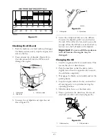
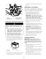
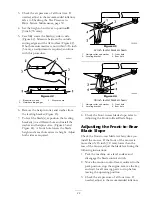
5. Measure the length of the rod extending out of
the adjusting block on the sides of the chassis
(Figure 45).
6. If the rod length is
not
a 3/4 inch (19 mm),
remove the hairpin cotter and washer from the
end of the adjusting rod (Figure 45) and turn
the rod until the 3/4 inch (19 mm) dimension
is obtained.
7. Install the end of the rod into the hole in the
mower mount and secure it with the washer
and hairpin cotter.
Figure 45
38 inch leveler bracket shown
1. Leveling bracket
3. Adjusting rod
2. Adjusting block
4. Hairpin cotter and washer
8. Repeat steps 5 through 7 for the opposite side
of the mower.
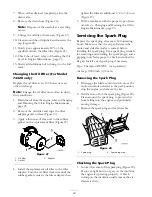
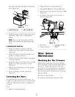
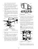
9. Set the height-of-cut at position
D
[3 inch
(76 mm)] and carefully rotate the blades so
they are facing front to rear (Figure 46).
10. Measure from the tip of the front blade to the
flat surface and the tip of the rear blade to the
flat surface (Figure 46). If the front blade tip
is not 1/16-5/16 inch (1.6-7.9 mm) lower than
the rear blade tip, adjust the front locknuts.
Figure 46
1. Blades front to rear
3. Measure here
2. Outside cutting edges
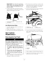
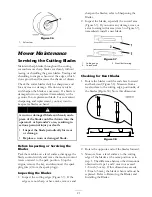
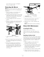
11. To adjust the front-to-rear blade slope, remove
the locknuts and then rotate the adjustment
nuts in the front of the mower (Figure 47).
12. To raise the front of the mower, tighten the
adjustment nuts. To lower the front of the
mower, loosen the adjustment nuts.
13. After adjusting both adjustment nuts evenly,
check the front-to-rear slope again. Continue
adjusting the nuts until the front blade tip is
1/16-5/16 inch (1.6-7.9 mm) lower than the
rear blade tip (Figure 47).
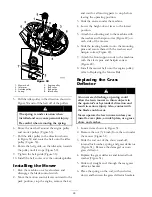
Note:
After adjusting the adjustment nuts,
make sure there is no slack in either support
rod (Figure 48). Tighten either one to remove
the slack (Figure 47).
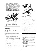
Figure 47
1. Locknut and adjusting nut 3. Adjustment nut
2. Front tire
4. Lock nut
14. When the front-to-rear blade slope is correct,
tighten the lock nuts and check the side-to-side
34
Содержание TimeCutter Z380
Страница 8: ...Slope Chart 8 ...
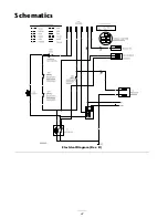
Страница 42: ...Schematics Electrical Diagram Rev B 42 ...

