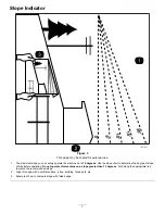
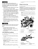
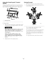

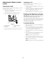

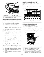


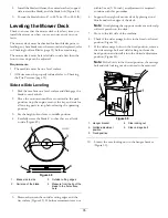

g017303
1 2
3
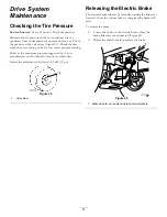
Figure 24
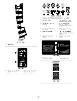
1.
Bypass-lever locations
3.
Lever position for pushing
the machine
2.
Lever position for
operating the machine
6.
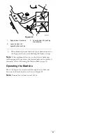
When finished, ensure that the key has been returned to
the Stop position to avoid draining the battery charge.
Note:
If the machine fails to move, the electric brake may
still be engaged. If necessary, the electric brake can be released
manually; refer to Releasing the Electric Brake (page 31).
Operating the Machine
Move the bypass levers rearward through the key hole and
down to lock them in place as shown in Figure 24.
Note:
Ensure this is done for each lever.
21
Содержание TimeCutter SS 3216
Страница 44: ...Schematics G014644 Electrical Diagram Rev A 44 ...
Страница 45: ...Notes 45 ...
Страница 46: ...Notes 46 ...
Страница 47: ...Notes 47 ...


