Toro ProCore Скачать руководство пользователя страница 99

ProCore Processor

Page 6 -- 23

Chassis

7. Adjust drive belt idler pulleys to achieve proper ten-

sion on drive belts (see Operator’s Manual). After ad-

justment, make sure that chopper axle and brush shaft

are still properly aligned (Fig. 23).

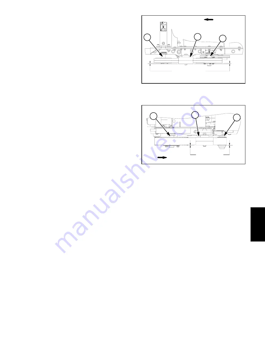
IMPORTANT: After adjusting belt tension, check

that distance from idler pulley face to the faces of

the drive and driven pulleys is correct (Figs. 24 and

25). This distance is necessary to ensure that idler

pulley is correctly aligned to drive belts. If neces-

sary, re--adjust positions of drive and driven pulleys

to allow correct distance.

8. Install belt covers (see Drive Belt Covers in this sec-

tion).

9. Install rear cover to machine (see Rear Cover Instal-

lation in this section).

1. Jack shaft

2. Chopper axle

3. Idler pulley

Figure 24

0.250” (6.3 mm)

Idler Face to Sheave Face

1

2

3

FRONT

1. Brush shaft

2. Chopper axle

3. Idler pulley

Figure 25

0.050” (1.3 mm)

Idler Face to Sheave Face

UP

1

2

3

Chassis

Содержание ProCore

Страница 1: ...ete Model and Serial Number to The Toro Company Attn Technical Publications 8111 Lyndale Avenue South Minneapolis MN 55420 The Toro Company reserves the right to change product specifications or this...

Страница 2: ...ProCore Processor This page is intentionally blank...

Страница 3: ...R MANUAL Chapter 4 Hydraulic System General Information 4 2 Special Tools 4 7 Hydraulic Schematics 4 8 Hydraulic Flow Diagrams 4 10 Troubleshooting 4 14 Testing 4 17 Service and Repairs 4 20 Chapter 5...

Страница 4: ...ProCore Processor This page is intentionally blank...

Страница 5: ...sor Chapter 1 Safety Table of Contents SAFETY INSTRUCTIONS 2 Before Operating 2 While Operating 2 Maintenance and Service 3 JACKING INSTRUCTIONS 4 SECURING PROCORE PROCESSOR TO TOW VEHICLE 4 SAFETY AN...

Страница 6: ...achine Also tighten any loose nuts bolts or screws to ensure machine is in safe operating condition 3 Make sure that the tow vehicle is carefully selected to assure the best performance and safe opera...

Страница 7: ...rts on the ProCore Processor Keep bystanders away 9 Do not overspeed the engine by changing governor setting To assure safety and accuracy check maximum engine speed with a tachometer 10 Shut ProCore...

Страница 8: ...axle to frame with hitch pin and lynch pin to prevent lift axle from shifting Fig 1 3 Position jack securely under the main frame Do not use the lift axle as a jacking point 4 Carefully jack machine o...

Страница 9: ...d Steel Fasteners Metric Fasteners 5 Other Torque Specifications 6 Conversion Factors 6 Product Records Insert Operator s Manual and Parts Catalog for your ProCore Processor at the end of this chapter...

Страница 10: ...0 09375 ProCore Processor Page 2 2 Product Records and Maintenance Equivalents and Conversions...

Страница 11: ...t and mating part then back off fastener 1 4 of a turn Measure the torque required to tighten the fastener until the lines match up Fastener Identification Figure 1 Grade 1 Grade 5 Grade 8 Inch Series...

Страница 12: ...2 22 3 30 3 41 4 43 5 58 7 3 8 24 UNF 17 2 18 2 24 3 35 4 47 5 50 6 68 8 7 16 14 UNC 27 3 27 3 37 4 50 5 68 7 70 7 95 9 7 16 20 UNF 29 3 29 3 39 4 55 6 75 8 77 8 104 11 1 2 13 UNC 30 3 48 7 65 9 75 8...

Страница 13: ...90 10 N m 93 10 ft lb 126 14 N m M16 X 2 0 166 17 ft lb 225 23 N m 229 23 ft lb 310 31 N m M20 X 2 5 325 33 ft lb 440 45 N m 450 46 ft lb 610 62 N m NOTE Reduce torque values listed in the table abov...

Страница 14: ...n lb Wheel Bolts and Lug Nuts Thread Size Recommended Torque 7 16 20 UNF Grade 5 65 10 ft lb 88 14 N m 1 2 20 UNF Grade 5 80 10 ft lb 108 14 N m M12 X 1 25 Class 8 8 80 10 ft lb 108 14 N m M12 X 1 5 C...

Страница 15: ...S 2 GENERAL INFORMATION 3 Operator s Manual 3 SPECIAL TOOLS 4 Centrifugal Clutch Puller 4 SERVICE AND REPAIRS 5 Cooling System 5 Air Cleaner 6 Fuel Tank 8 Centrifugal Clutch 10 Engine 12 Engine Remova...

Страница 16: ...o load 1550 100 RPM High Idle Speed no load 3600 100 RPM Carburetor Float feed 2 barrel fixed main jet Fuel Pump Mechanical Fuel Unleaded regular grade gasoline Air Cleaner Cyclonic multi stage Lubric...

Страница 17: ...of some specialized test equipment is explained However the cost of the test equipment and the specialized nature of some repairs may dictate that the work be done at an en gine repair facility Servi...

Страница 18: ...Fig 1 1 To protect the engine crankshaft place thick washer on end of crankshaft and lightly grease the end of the ro tator pin 2 Thread puller stator base item 2 into bore of centrif ugal clutch 3 T...

Страница 19: ...system 2 Remove front panel Fig 2 to allow cleaning around intake manifold fuel pump carburetor and governor linkage 3 Clean blower housing of dirt and debris Fig 2 Re move blower housing from engine...

Страница 20: ...nnerman nut 2 used 4 Air cleaner assembly 5 Flat washer 4 used 6 Cap screw 6 mm 2 used 7 Air cleaner bracket 2 used 8 Air cleaner cap 9 Clamp 10 Service indicator 11 Nipple 12 Air intake hose 13 Hose...

Страница 21: ...into engine and will cause serious engine damage Make sure that all air cleaner components are in good condition and are properly secured dur ing assembly 1 Assemble all removed air cleaner components...

Страница 22: ...5 10 5 DANGER Because gasoline is highly flammable use cau tion when storing or handling it Do not smoke while filling the fuel tank Do not fill fuel tank while engine is running hot or when machine i...

Страница 23: ...rk plug wires from the spark plugs to prevent the engine from starting unexpectedly 2 Use a fuel transfer pump to remove fuel from the fuel tank and into a suitable container 3 Disconnect fuel hose fr...

Страница 24: ...Fig 8 1 Make sure machine is parked on a level surface with the engine OFF Remove key from ignition switch Chock wheels to prevent movement of machine Re move spark plug wires from the spark plugs to...

Страница 25: ...belts see Operator s Manual IMPORTANT After adjusting belt tension check that distance from idler pulley face to the faces of the clutch drive pulley and jack shaft driven pulley is correct Fig 9 This...

Страница 26: ...sher 2 used 23 Tinnerman nut 24 Cap screw 2 used 25 Cap screw 26 Belt guard 27 Cap screw 6 mm 2 used 28 Flat washer 4 used 29 Muffler mount 30 Belt cover 31 Flat washer 8 used 32 Muffler guard 33 Air...

Страница 27: ...engine see Air Cleaner Removal in this section 10 Remove muffler guard item 32 belt guard item 26 and belt cover item 30 see Drive Belt Covers in the Service and Repairs section of Chapter 6 Chassis M...

Страница 28: ...RTANT After adjusting belt tension check that distance from idler pulley face to the faces of the clutch drive pulley and jack shaft driven pulley is correct Fig 14 This distance is necessary to en su...

Страница 29: ...HYDRAULIC SCHEMATICS 8 Hydraulic Schematic 8 Hydraulic Schematic With Tow Hitch Kit 9 HYDRAULIC FLOW DIAGRAMS 10 Raise and Lower Circuits 10 Tow Hitch Circuits When Equipped With Tow Hitch Kit 12 TRO...

Страница 30: ...changing tow vehicles or trac tors make sure that the tow vehicle hydraulic fluid is compatible with the ProCore Processor fluid If the fluids are not compatible any fluid remaining in the core proce...

Страница 31: ...Use two wrenches hold the hose straight with one wrench and tighten the hose swivel nut onto the fit ting with the other wrench See Hydraulic Hose and Tube Installation in this section If the hose has...

Страница 32: ...t Wrench in the Torque Specifica tions section of Chapter 2 Product Records and Main tenance 5 If a torque wrench is not available or if space at the swivel nut prevents use of a torque wrench an alte...

Страница 33: ...ds and Maintenance to determine necessary con version information 5 If a torque wrench is not available or if space at the port prevents use of a torque wrench an alternate meth od of assembly is the...

Страница 34: ...osition with a wrench and use a torque wrench to tighten the fitting to the rec ommended installation torque shown in Figure 6 This tightening process will require the use of an offset wrench e g crow...

Страница 35: ...A high pressure hose is provided for remote readings Contains one each 1000 PSI 70 Bar 5000 PSI 350 Bar and 10000 PSI 700 Bar gauges Use gauges as recommended in the Testing section of this chapter F...

Страница 36: ...Hydraulic Schematics Hydraulic Schematic ProCore Processor NOTE For identification purposes the hydraulic hose to lift relief manifold port A is equipped with a cable tie at the Core Processor quick...

Страница 37: ...lenoids are shown as de energized With Tow Hitch Kit LIFT RELIEF MANIFOLD TOW HITCH MANIFOLD OFFSET CYLINDER LIFT CYLINDER NOTE For identification purposes the hydraulic hose to lift relief manifold p...

Страница 38: ...Flow Raise and Lower Circuits LIFT RELIEF MANIFOLD LIFT CYLINDER EXTENDING RAISE NOTE For identification purposes the hydraulic hose to lift relief manifold port A is equipped with a cable tie at the...

Страница 39: ...Processor is raised is limited to 1100 PSI 76 Bar by the raise relief valve RV1 in the lift relief manifold Lower Fig 11 When the tow vehicle control is positioned to lower the ProCore Processor oil...

Страница 40: ...Flow Tow Hitch Circuits Remote Control Switch in Lift Position Tow Vehicle Control in Raise Position LIFT CYLINDER EXTENDING Figure 13 All manifold de energized solenoids are NOTE For identification...

Страница 41: ...anifold are energized In this position hy draulic oil flow from the tow vehicle is available for the ProCore Processor hitch offset function via solenoid valves S3 and S4 Hydraulic flow to the lift cy...

Страница 42: ...tting s or hose s are loose or damaged O ring s or seal s are missing or damaged Foaming hydraulic fluid Hydraulic oil level in tow vehicle reservoir is low Hydraulic system has wrong kind of oil Hydr...

Страница 43: ...is malfunctioning ProCore Processor Tow Hitch offset not operating machines with Tow Hitch Remote control lift offset switch is not in offset position An electrical problem exists see Chapter 5 Elect...

Страница 44: ...ProCore Processor Hydraulic System Page 4 16 This page is intentionally blank...

Страница 45: ...injected into the skin it must be surgically removed within a few hours by a doctor familiar with this type of injury Gangrene may result from such an injury WARNING 1 Thoroughly clean the machine bef...

Страница 46: ...and Lower Relief LIFT RELIEF MANIFOLD LIFT CYLINDER EXTENDING RAISE LIFT RELIEF MANIFOLD LIFT CYLINDER RETRACTING LOWER PRESSURE GAUGE PRESSURE GAUGE Valve Pressure Test NOTE For identification purpo...

Страница 47: ...e to full speed IMPORTANT While performing this test hold tow vehicle lift lever in the raise lower position only long enough to get a relief pressure reading Holding the lever in the raise lower posi...

Страница 48: ...hydraulic lines and hoses for proper installation after repairs are completed 5 Note the position of hydraulic fittings especially el bow fittings on hydraulic components before removal Mark parts if...

Страница 49: ...can have sufficient force to penetrate the skin and cause serious injury If fluid is in jected into the skin it must be surgically re moved within a few hours by a doctor familiar with this type of in...

Страница 50: ...ines on a level surface Secure lift axle to frame with hitch pin and lynch pin to prevent lift axle from shifting Engage vehicle parking brake stop engine and remove key from the ignition switch Make...

Страница 51: ...es as fine as talcum powder can affect the operation of the valve Be extremely careful to not damage cartridge Use compressed air for cleaning 5 Lubricate new cartridge valve seal kit components with...

Страница 52: ...used per wheel 3 Wheel assembly 4 Grease fitting 5 Lift cylinder 6 Pivot pin 7 Grease fitting 2 used 8 Shoulder bolt 9 Axle block 4 used 10 Flat washer 8 used 11 Cap screw 4 used 12 Lock nut 4 used 13...

Страница 53: ...ig 20 Discard O rings 12 Inspect bushing in axle and frame item 13 for wear or damage Replace bushing if necessary If bushing re placement is necessary position bushing as follows A Bushing in frame p...

Страница 54: ...Kit 1 Hydraulic offset cylinder 2 Cylinder pin 2 used 3 Flat washer 2 used 4 Cap screw 2 used 5 O ring 2 used 6 Hydraulic fitting 2 used 7 O ring 2 used 8 Flange nut 2 used 9 Hose from manifold port C...

Страница 55: ...Support offset cylinder and slide cylinder pins from the offset cylinder and machine frame 8 Remove offset cylinder from the machine 9 If needed remove fittings and O rings from the off set cylinder D...

Страница 56: ...drain pan by slowly pumping the cylinder rod Plug ports and clean the outside of the lift cylinder IMPORTANT Prevent damage when clamping the lift cylinder into a vise clamp on the pivot only 2 Mount...

Страница 57: ...ll O rings items 3 and 12 seal item 2 and wear ring item 1 to piston IMPORTANT Do not clamp vise jaws against rod surface Protect rod surface before mounting in vise 4 Mount rod securely in a vise by...

Страница 58: ...ld 3 O ring 4 Hydraulic fitting 5 used 5 O ring 6 Tow hitch manifold 7 Spacer 2 used 8 Flat washer 4 used 9 Cap screw 2 used 10 Lock nut 2 used 11 Hydraulic fitting with orifice 042 12 Hydraulic hose...

Страница 59: ...ness connectors from solenoid valve coils 8 Remove two 2 cap screws flat washers and lock nuts that secure manifold to machine frame Locate two 2 spacers used between manifold and frame 9 Remove tow h...

Страница 60: ...eating or there may be water in the system CAUTION Use eye protection such as goggles when using compressed air for cartridge valve cleaning 5 Clean valves by submerging valve in clean mineral spirits...

Страница 61: ...Test 6 Charging System Test 6 COMPONENT TESTING 7 Ignition Switch 7 Remote Control Handle Switches 8 Hour Meter 9 Fuses 9 Fusible Link 10 Solenoid Valve Coil Tow Hitch Kit 11 SERVICE AND REPAIRS 12 Ba...

Страница 62: ...e internalresistance ofa digitalme ter in the voltage mode will make sure that excess cur rent is not allowed through the meter This excess current can cause damage to circuits not designed to carry i...

Страница 63: ...ProCore Processor Page 5 3 Electrical System Battery Hydrometer Use the Battery Hydrometer when measuring specific gravity of battery electrolyte Obtain this tool locally Figure 4 Electrical System...

Страница 64: ...attery cables are loose or corroded Battery ground to frame is loose or corroded Wiring at starter is faulty Starter solenoid is faulty Starter is faulty Nothing happens when start attempt is made Bat...

Страница 65: ...tor is not properly grounded to engine Voltage regulator is faulty Ignition switch is faulty Alternator stator or engine flywheel is faulty Battery is faulty Engine kills during operation Ignition swi...

Страница 66: ...le test used to determine if a charging sys tem is functioning It will tell you if the charging system has an output but not its capacity Use a digital multimeter set to DC volts Connect the positive...

Страница 67: ...witch terminals are posi tioned as shown in Figure 6 Testing 1 Make sure that Processor ignition switch is in the OFF position Remove key from the ignition switch 2 Unplug wire harness connectors from...

Страница 68: ...ndle wire har ness can be checked by unplugging the handle wire har ness from the main wire harness of the ProCore Processor Using a Multimeter set to ohms test continu ity of the switches and remote...

Страница 69: ...from the hour meter 6 Replace the hour meter if necessary 7 Connect wire harness connector to hour meter Figure 11 QUARTZ Hobbs HOURS 1 0 0 0 0 1 10 BACK FRONT Fuses The ProCore Processor uses two 2 f...

Страница 70: ...onnect the positive cable from battery see Battery Service in the Service and Repairs section of this chap ter Locate and unplug fusible link connector from ma chine wire harness Use a multimeter to m...

Страница 71: ...ignition switch 2 Disconnect wire harness electrical connector from the solenoid valve coil that is to be tested NOTE Prior to taking small resistance readings with a digital multimeter short the tes...

Страница 72: ...ausea may result if the gases are inhaled Un plug charger from electrical outlet before con necting or disconnecting charger leads to or from battery posts CAUTION IMPORTANT Do not remove battery fill...

Страница 73: ...e battery post and the nega tive ground cable connector The reading should be less than 0 1 amp If the reading is 0 1 amp or more the machine s electrical system should be tested for short circuits or...

Страница 74: ...load tester This is one ofthe mostreliable means oftesting a battery as itsimulates the cold cranking test A commercialbat tery load tester is required to perform this test CAUTION Follow the battery...

Страница 75: ...5 8 hrs 6 amps 11 5 hrs 6 amps 17 3 hrs 6 amps 23 hrs 6 amps above 250 6 hrs 10 amps 12 hrs 10 amps 18 hrs 10 amps 24 hrs 10 amps CAUTION Do not charge a frozen battery because it can ex plode and ca...

Страница 76: ...removed 3 Remove nut that secures solenoid coil to solenoid valve 4 Slide solenoid coil from valve Installation Fig 17 1 Clean valve stem and solenoid coil bore 2 Slide coil onto solenoid valve 3 Secu...

Страница 77: ...ng ProCore Processor to Tow Vehicle 3 SERVICE AND REPAIRS 4 Wheels 4 Wheel Hubs and Bearings 6 Drive Belt Covers 8 Pulley Assembly Service 10 Flange Bearing Service 12 Jack Shaft Assembly 14 Chopper A...

Страница 78: ...n Transport Tires Size 18 x 9 5 8 6 Ply Tubeless Pressure 36 PSI 248 kPa Wheel Lug Nut Torque 70 to 90 ft lb 95 to 122 N m Brush Fig 1 Bristle Length New 4 500 114 3 mm Bristle Length Replace 3 500 88...

Страница 79: ...sor Refer to the Oper ator s Manual for additional information when servicing the machine Securing ProCore Processor to Tow Vehicle While operating or servicing the ProCore Processor make sure that th...

Страница 80: ...ssor Page 6 4 Chassis Service and Repairs Wheels 1 Main frame 2 Lug nut 5 used per wheel 3 Wheel and tire assembly 4 Lift axle 5 Hitch pin 6 Lynch pin Figure 2 FRONT RIGHT 1 2 3 70 to 90 ft lb 95 to 1...

Страница 81: ...cure wheel to be removed 4 Jack or hoist Processor from ground and support machine with jack stands see Operator s Manual and Jacking Instructions in Chapter 1 Safety 5 Remove lug nuts and pull wheel...

Страница 82: ...gure 3 1 Lift axle 2 Grease seal 3 Inner bearing cone 4 Inner bearing cup 5 Wheel hub 6 Lug screw 5 used 7 Outer bearing cup 8 Outer bearing cone 9 Washer 10 Cotter pin 11 Slotted hex nut 12 Dust cup...

Страница 83: ...re assembly 2 Assemble wheel hub A If bearing cups were removed from the wheel hub press inner and outer cups into the hub until they seat against the hub shoulder B Fill hub approximately 50 full of...

Страница 84: ...nut 7 used 4 Jack shaft 5 Idler pulley 6 Belt cover 7 Jack shaft pulley 8 Muffler guard 9 Cap screw 12 used 10 Flat washer 12 used 11 Flange nut 3 used 12 Tinnerman nut 13 Belt guard 14 Belt set 15 F...

Страница 85: ...ain access to drive belt and other drive components Make sure that tinnerman nuts remain positioned correctly on frame brackets for assembly purposes Installation Figs 4 5 and 6 1 Position belt cover...

Страница 86: ...re key 4 Taper lock bushing 5 Cap screw 3 used 6 Lock washer 3 used 7 Set screw if equipped 8 Cap screw 3 used 9 Lock washer 3 used 10 Taper lock bushing 11 Square key 12 Pulley Figure 7 FRONT RIGHT 6...

Страница 87: ...i seize lubricant to square key and place key into shaft slot 2 Make sure that tapered surfaces of pulley and taper lock bushing are thoroughly clean no oil grease dirt rust etc 3 Slide pulley and tap...

Страница 88: ...per bearing 8 Screw 4 used per bearing 9 Taper lock bushing 10 Pulley 11 Shaft jack shaft shown 12 Idler pulley Figure 8 FRONT RIGHT 6 7 3 2 5 4 1 8 9 10 3 11 Light Oil 2 6 7 Light Oil 8 12 CHOPPER AX...

Страница 89: ...e resistance 5 Secure bearing to machine frame with removed fas teners 6 Position the bearing collar so that a set screw is di rectly opposite the split in the sleeve Fig 9 Tighten three 3 bearing set...

Страница 90: ...ount 29 Carriage screw 30 Standoff 31 Carriage screw 32 Cap screw 3 used per bushing 33 Cap screw 3 used per bushing 34 Centrifugal clutch 35 Engine Figure 10 FRONT RIGHT 29 30 23 28 12 22 27 3 32 11...

Страница 91: ...alling 7 On both ends of jack shaft remove bearing A Loosen three 3 set screws that secure bearing collar to jack shaft B Note location of grease fitting on jack shaft bear ing so bearing can be prope...

Страница 92: ...eft end of jack shaft drive side align pulley and drive belt with driven pulley on chopper axle 7 Install square key pulley taper lock bushing and drive belt to both ends of jack shaft see Pulley Asse...

Страница 93: ...ProCore Processor Page 6 17 Chassis This page is intentionally blank Chassis...

Страница 94: ...roCore Processor Page 6 18 Chassis Chopper Axle Service 1 Cap screw 62 used 2 LH blade assembly 31 used 3 Lock nut 62 used 4 RH blade assembly 31 used 5 Chopper axle Figure 16 FRONT RIGHT 3 2 5 4 1 3...

Страница 95: ...s beyond the chopper tip Apply heat to thread area of chopper tip and use a flat blade screwdriver to remove the broken screw 2 To remove chopper tip s from blade use a ratchet ing box wrench to remov...

Страница 96: ...washer 3 used 30 Cap screw 3 used 31 Cap screw 3 used 32 Taper lock bushing 33 Pulley 34 Lock washer 3 used 35 Set screw Figure 19 FRONT RIGHT 333 to 387 in lb 38 to 43 N m Antiseize Lubricant Antisei...

Страница 97: ...ate and retrieve square key item 16 7 Remove four 4 screws washers and lock nuts that secure reinforcing ring item 8 to chopper housing Fig 22 Remove reinforcing ring CAUTION To prevent personal injur...

Страница 98: ...nd drive beltto rightend of chopper axle A Apply antiseize lubricant to square key and place key in chopper axle slot B Slide sprocket onto chopper axle Do not tighten set screws in sprocket IMPORTANT...

Страница 99: ...is correct Figs 24 and 25 This distance is necessary to ensure that idler pulley is correctly aligned to drive belts If neces sary re adjust positions of drive and driven pulleys to allow correct dist...

Страница 100: ...lock bushing 33 Square key 34 Pulley 35 Pulley rotating corner shaft 36 Square key 37 Set screw 2 used per pulley 38 Drive belt 39 Square key 40 Pulley brush shaft Figure 26 FRONT RIGHT 3 2 12 5 6 13...

Страница 101: ...t flange bear ing to brush housing 8 Raise Processor while allowing brush assembly to remain on the ground Support Processor to prevent it from lowering 9 Remove brush assembly from under machine 10 L...

Страница 102: ...t with driven pulley on rotating corner shaft 11 Install square key pulley taper lock bushing and drive belt to left end of brush shaft see Pulley Assembly Service in this section 12 Adjust drive belt...

Страница 103: ...ProCore Processor Page 6 27 Chassis This page is intentionally blank Chassis...

Страница 104: ...rner shaft is delivered on the left side of the machine from the brush shaft by an A section belt An adjustable idler pulley maintains belt tension Removal Fig 33 1 Park ProCore Processor on a level s...

Страница 105: ...t is 1 960 49 8 mm from side of machine frame Fig 35 NOTE Corner shaft rotates counterclockwise as viewed from right side of machine 5 Using the blind hole in flange mount bearing locking collars as a...

Страница 106: ...Operator s Manual IMPORTANT After adjusting belt tension check that the faces of the idler drive and driven pulleys are all in alignment Fig 36 This is necessary to en sure that idler pulley is correc...

Страница 107: ...ProCore Processor Page 6 31 Chassis This page is intentionally blank Chassis...

Страница 108: ...9 Set screw 10 Flange mount bearing 2 used 11 Carriage bolt 4 used 12 Carriage screw 2 used 13 Lock nut 6 used 14 Cap screw 2 used 15 Lock nut 4 used 16 Flat washer 7 used 17 Carriage screw 4 used Fig...

Страница 109: ...djustment plates and adjuster keys for assembly purposes B Remove flange nuts flat washers and carriage screws that secure roller adjustment plates and ad juster keys to frame Installation Fig 38 1 If...

Страница 110: ...olt 9 Axle block 4 used 10 Flat washer 11 Cap screw 4 used 12 Lock nut 13 Bushing 2 used 14 Screw 2 used 15 Cap screw 4 used 16 Grease fitting 2 used 17 Bearing tube 2 used 18 Lynch pin 2 used 19 Hitc...

Страница 111: ...n Fig 39 NOTE Bearing tubes should be installed on lift axle with bracket flange toward end of lift axle tube 1 Slide bearing tubes onto lift axle Secure each bear ing tube to lift axle with hitch pin...

Страница 112: ...lange nut 36 used 6 Carriage screw 2 used 7 Flat washer 30 used 8 Cap screw 47 used 9 Pivot 2 used 10 Pivot 2 used 11 Tinnerman nut 19 used 12 Cap screw 14 used 13 Flat washer 33 used 14 Backing plate...

Страница 113: ...re 38 as a guide Installation Fig 38 1 Assemble rear cover using Figure 38 as a guide 2 Position rear cover assembly to machine 3 Secure rear cover to machine A Secure rear cover pivot components item...

Страница 114: ...ProCore Processor Page 6 38 Chassis This page is intentionally blank...

Страница 115: ...lectrical Diagrams Table of Contents ELECTRICAL SCHEMATIC Electrical Schematic 3 CIRCUIT DRAWINGS Crank Circuits 4 Run Circuits 5 WIRE HARNESS DRAWINGS Wire Harness Drawing 6 Wire Harness Diagram 7 To...

Страница 116: ...ProCore Processor Electrical Diagrams Page 7 2 This page is intentionally blank...

Страница 117: ...RED PINK BLACK YELLOW GRAY ORANGE BROWN BROWN GRAY RED BLACK SWITCH 25 AMP FUSIBLE LINK MAIN SOLENOID FUSE ALT HOUR MAGNETOS METER A B REG BATTERY 10 AMP RUN FUSE FUEL D E C REMOTE STARTER INTERCONNE...

Страница 118: ...ED PINK BLACK YELLOW GRAY ORANGE BROWN BROWN GRAY RED BLACK SWITCH 25 AMP FUSIBLE LINK SOLENOID S1 MAIN SOLENOID FUSE ALT HOUR MAGNETOS METER A B REG BATTERY 10 AMP RUN FUSE FUEL D E C REMOTE STARTER...

Страница 119: ...ED PINK BLACK YELLOW GRAY ORANGE BROWN BROWN GRAY RED BLACK SWITCH 25 AMP FUSIBLE LINK MAIN SOLENOID FUSE OFFSET ALT HOUR MAGNETOS METER A B REG BATTERY 10 AMP RUN FUSE FUEL LIFT D E C REMOTE SWITCH S...

Страница 120: ...Page 7 6 ProCore Processor Wire Harness Drawing...

Страница 121: ...Page 7 7 ProCore Processor Wire Harness Diagram BROWN RED BLACK BLACK GRAY YELLOW BLACK ORANGE BROWN GREEN PINK BLUE BLACK GRAY GRAY BLACK GRAY BROWN RED BLUE GREEN PINK ORANGE YELLOW...

Страница 122: ...Page 7 8 ProCore Processor Tow Hitch Kit Wire Harness BLACK BLUE BLACK BLUE BLACK BLUE BLACK BLUE BLACK BLUE...

Отзывы: