
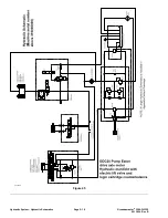


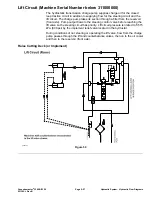


Lift Circuit (Machine Serial Number above 311000000)
The charge pump supplies charge fluid for the closed loop traction circuit in
addition to supplying flow for the steering circuit and the lift circuit. The charge
pump takes its suction through a filter from the transaxle reservoir (front axle).
The pump output flows to the steering control valve before reaching the lift
manifold so that the steering circuit has priority. When the lift switch is not set to
raise or lower, fluid flow enters the lift manifold at the P port. Hydraulic pressure
will try and raise the lift arms until the logic cartridge LC shifts open and provides
a fluid path to the tank (front axle). When the logic cartridge opens is controlled
by adjusting the logic cartridge to the desired setting or counterbalance. Refer
to the traction unit
Operator’s Manual
for additional counterbalance adjustment
information.
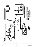
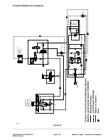
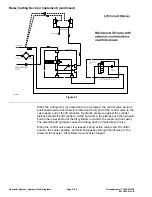
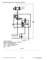
Raise the Cutting Deck (or Implement)
When the lift switch is set to the Raise position, solenoid valve SV1 is energized,
holding logic cartridge LC closed. Hydraulic flow is directed through solenoid
valve SV2 to the cap end (top) of the lift cylinders. When the cylinders reach the
end of their stroke, or if the lift arms are prevented from raising, the charge pump
relief valve in the hydraulic pump opens and directs the hydraulic flow to the tank
(front axle) until the lift switch is released.
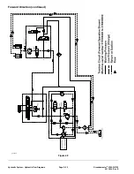
The hydraulic pressure against the cylinder pistons extends the lift cylinders. At
the same time, the pistons push the hydraulic fluid in the lower portion of the
lift cylinders out and to the hydraulic reservoir (front axle). The extending lift
cylinders cause the cutting deck (or implement) to raise.
Groundsmaster
®
3280-D/3320
Page 5–31
Hydraulic System: Hydraulic Flow Diagrams
05138SL Rev B
Содержание Groundsmaster 3280-D
Страница 4: ...NOTES Revision History Page 4 Groundsmaster 3280 D 3320 05138SL Rev B ...
Страница 10: ...Preface Page 10 Groundsmaster 3280 D 3320 05138SL Rev B ...
Страница 34: ...Specifications and Maintenance Special Tools Page 2 18 Groundsmaster 3280 D 3320 05138SL Rev B ...
Страница 56: ...Gasoline Engine Service and Repairs Page 3 22 Groundsmaster 3280 D 3320 05138SL Rev B ...
Страница 84: ...Diesel Engine Service and Repairs Page 4 28 Groundsmaster 3280 D 3320 05138SL Rev B ...
Страница 100: ...g229581 Figure 43 Hydraulic System Hydraulic Schematics Page 5 16 Groundsmaster 3280 D 3320 05138SL Rev B ...
Страница 101: ...g243934 Figure 44 Groundsmaster 3280 D 3320 Page 5 17 Hydraulic System Hydraulic Schematics 05138SL Rev B ...
Страница 102: ...g224768 Figure 45 Hydraulic System Hydraulic Schematics Page 5 18 Groundsmaster 3280 D 3320 05138SL Rev B ...
Страница 228: ...Hydraulic System Service and Repairs Page 5 144 Groundsmaster 3280 D 3320 05138SL Rev B ...
Страница 430: ...PTO System Service and Repairs Page 9 12 Groundsmaster 3280 D 3320 05138SL Rev B ...
Страница 466: ...Operator Cab Service and Repairs Page 11 16 Groundsmaster 3280 D 3320 05138SL Rev B ...
Страница 470: ...Foldout Drawings Page A 4 Groundsmaster 3280 D 3320 05138SL Rev B ...
Страница 478: ...Page A 12 05138SL Rev B Operator Cab Drawing 122 0426 Rev A Sheet 1 of 2 Electrical Schematic Operator Cab g226449 ...
Страница 479: ...Operator Cab Drawing 122 0426 Rev A Sheet 2 of 2 05138SL Rev B Page A 13 Electrical Schematic Operator Cab g226450 ...
Страница 508: ......


