


CAN bus Communications
The machine controllers communicate with each other on a Controller Area
Network (CAN) bus system. Using this network allows full integration of all the
different electrical components of the machine, allowing them to operate together
as one. The integration of the controllers allows the InfoCenter display to
access machine settings, calibrate various machine components, and assist with
electrical system diagnostics. The key switch needs to be in the R
UN
or S
TART
position for the components on the network to be activated.
Controllers that operate on 12 VDC connect to the 12V side of the CAN bus
(CAN A), while controllers that operate on 48 VDC connect to the 48V side of the
CAN bus (CAN B). The two sides of the CAN bus communicate as one network
through the use of a CAN bus Isolation Module.
IMPORTANT
Logic voltage must be present at the controller before communication
with that controller can occur on the CAN bus.
The entire CAN bus is made up of two specially designed twisted wires. The
engineering term for these wires are CAN High (yellow wire) and CAN Low
(green wire). A 120 ohm CAN termination resistor is located at each end of
CAN A, and at each end of CAN B (4 total). Refer to
for
CAN bus testing procedures.
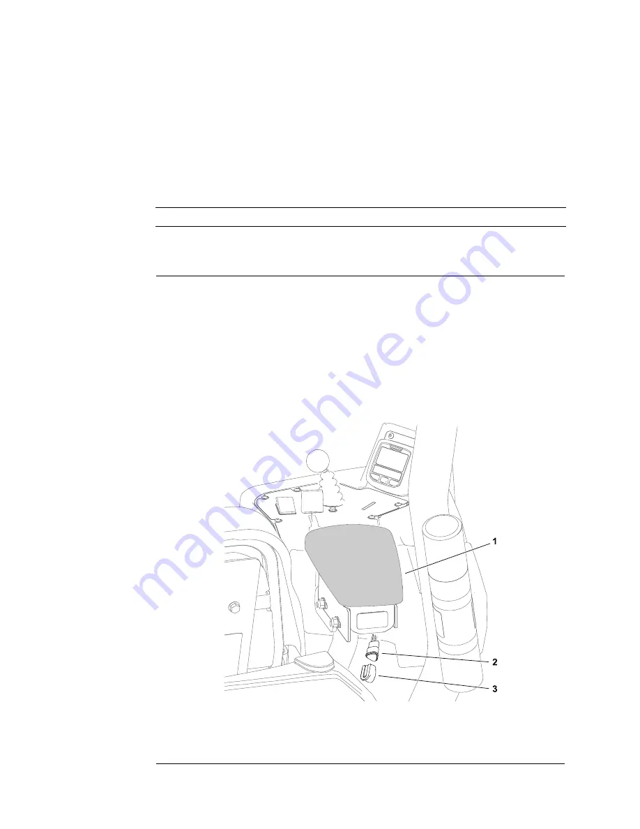
The Toro DIAG electronic control diagnostics service system is available to
Authorized Toro Distributors to support machine fault diagnosis and maintenance
services of the machine electrical control devices. The Toro DIAG connector is
part of the CAN bus and is located at the rear of the console armrest.
g287537
Figure 23
1.
Console armrest
3.
Connector cover
2.
Toro DIAG connector
Electrical System: Electrical System Operation
Page 5–12
Greensmaster® eTriFlex 3360 and 3370
19239SL Rev B
Содержание Greensmaster eTriFlex 3360
Страница 4: ...Reader Comments Page 4 Greensmaster eTriFlex 3360 and 3370 19239SL Rev B...
Страница 16: ...Safety Safety and Instructional Decals Page 1 8 Greensmaster eTriFlex 3360 and 3370 19239SL Rev B...
Страница 36: ...Specifications and Maintenance Special Tools Page 2 20 Greensmaster eTriFlex 3360 and 3370 19239SL Rev B...
Страница 298: ...Chassis Service and Repairs Page 6 52 Greensmaster eTriFlex 3360 and 3370 19239SL Rev B...
Страница 334: ...DPA Cutting Units Service and Repairs Page 7 36 Greensmaster eTriFlex 3360 and 3370 19239SL Rev B...
Страница 354: ...Universal Groomer Optional Service and Repairs Page 8 20 Greensmaster eTriFlex 3360 and 3370 19239SL Rev B...
Страница 357: ...Model 04580 Drawing 122 0142 Rev A Sheet 1 of 1 19239SL Rev B Page A 3 Electrical Schematic 3360 g291901...
Страница 358: ...Page A 4 19239SL Rev B Model 04590 Drawing 122 1618 Rev A Sheet 1 of 2 Electrical Schematic 3370 g309035...
Страница 359: ...Model 04590 Drawing 122 1618 Rev A Sheet 2 of 2 19239SL Rev B Page A 5 Electrical Schematic 3370 continued g309036...
Страница 360: ...Page A 6 19239SL Rev B Model 04580 Drawing 122 1619 Rev D Sheet 1 of 1 Wire Harness Drawing 3360 g287361...
Страница 361: ...Model 04580 Drawing 122 1619 Rev D Sheet 1 of 2 19239SL Rev B Page A 7 Wire Harness Diagram 3360 g293957...
Страница 362: ...Page A 8 19239SL Rev B Model 04580 Drawing 122 1619 Rev D Sheet 2 of 2 Wire Harness Diagram 3360 continued g293958...
Страница 363: ...Model 04580 Drawing 122 1620 Rev D Sheet 1 of 1 19239SL Rev B Page A 9 Wire Harness Drawing 3370 g309034...
Страница 364: ...Page A 10 19239SL Rev B Model 04590 Drawing 122 1620 Rev D Sheet 1 of 2 Wire Harness Diagram 3370 g309032...
Страница 365: ...Model 04590 Drawing 122 1620 Rev D Sheet 2 of 2 19239SL Rev B Page A 11 Wire Harness Diagram 3370 continued g309033...
Страница 366: ......


