background image

Note

The GreenKeeper 212 controller is not weather

resistant and must be installed indoors or in a pro-
tected area. 

For outdoor installation, a weather-resistant outdoor cabi-
net is available. Order model number GK212-CAB-01 for
domestic controllers or GK212-CAB-02 for export 
controllers.

1. Select a location for the controller within 4' (1.2m) of

an electrical outlet to enable the transformer wires to
easily reach. Make sure the outlet is not controlled by
a light switch.

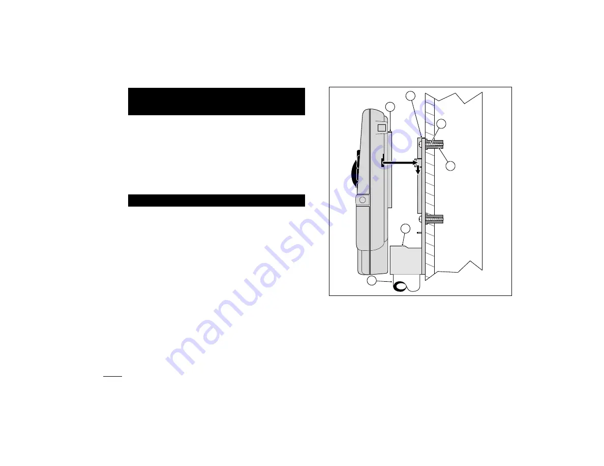
2. Remove the mounting bracket attached to the back 

of the controller housing by pulling the lower edge of
the bracket away and downward from the controller
housing.

3. Place the mounting bracket (A) against the wall align-

ing the top edge at about eye level. Drive three 1"
(25mm) wood screws (B) into the wall through the
three holes provided in the bracket.

Note

: If you are installing the bracket on drywall or

masonry, install screw anchors (C) to prevent screws
from loosening.

4.

Optional

- Insert 3/4" (19mm) PVC conduit (D) for

valve wiring into bracket sleeve (E).

5. Align the slotted openings on the back of controller

housing with the mounting bracket tabs. Slide the
controller downward to engage the tabs.

Note:

After installation, store the Quick Reference

Guide and the Watering Schedule Form in the 
pocket (F) behind the controller.

Mounting The Controller

Installation

22

B

C

F

A

E

Содержание Green Keeper 212

Страница 1: ...dules 3 Watering Programs With Calendar Interval and Odd Even Days 1 Min to 4 Hrs Zone Run Time 4 Start Times Per Program Battery Back Up Automatic Pump Start Seasonal Run Time Adjust Rain Delay Rain...

Страница 2: ......

Страница 3: ...le 17 Setting An Interval Schedule 18 Setting An Odd or Even Schedule 19 Turning Off A Program 19 Setting Program Start Times 20 Setting Station Run Times 21 Installation Mounting The Controller 22 Co...

Страница 4: ...Controller Components GreenKeeper 212 Introduction and Set Up 2 1 3 BATTERY 2...

Страница 5: ...on numbers J Percent symbol Indicates the Season Adjust feature is in use K Day of the week identifiers L Run Time symbol Hourglass is displayed when setting the watering station run times 2 Control B...

Страница 6: ...provided for Alkaline and rechargeable batteries 10 Rain Sensor Control Switch Controls the sensor input circuit Switch positions provided for sensor circuit On and Off 11 Sensor Connection Terminals...

Страница 7: ...5 BATTERY 16 17 18 5 6 7 10 11 12 13 14 9 8 15 3 4 Controller Components...

Страница 8: ...ithin the controller identifying it as Station 1 Station 2 etc The controller operates the valves in order one at a time In other words one station would water completely before another station would...

Страница 9: ...roller skips station 3 and turns on station 4 which runs for 20 minutes and shuts off Station 5 is skipped and the watering cycle ends at 5 40 AM As you can see from this example only one program star...

Страница 10: ...tering every sev enth day Once you have selected an Interval schedule you can choose which day of the week will be the first day of the Interval The number of days in the Interval deter mines the avai...

Страница 11: ...ime is displayed In this example program A has one start time start time number 1 set for 5 00 AM Setting The Station Run Time A station run time is the length of time the station con trolled by the v...

Страница 12: ...nd make program adjustments immediately Filling Out The Watering Schedule Form When filling out this form use a pencil so changes can be easily made Carefully remove the page from the booklet to use a...

Страница 13: ...11 Example...

Страница 14: ...4 5 6 7 8 9 10 11 12 2 3 4 5 6 7 1 2 3 4 5 6 7 1 2 3 4 5 6 7 CALENDAR LOCATION ZONE ZONE RUN TIME ZONE RUN TIME ZONE RUN TIME WATERING DAY SCHEDULE INTERVAL ODD ODD EVEN EVEN PROGRAM START TIMES 1 2 3...

Страница 15: ...ttery into the cabinet compartment as shown in Figure 1 2 The display will begin flashing 12 00 AM Press the ON button to stop the display from flashing The colon will continuously flash while display...

Страница 16: ...ering sched ule within its memory to assist you in two ways First it will restore watering operation in case your watering pro gram is lost due to a power interruption lasting longer than the battery...

Страница 17: ...ements are quite different than the permanent values Note When power is first applied the GreenKeeper 212 will always reset to the permanent program values To Reset The Permanent Program Figure 4 Turn...

Страница 18: ...tep 5 Refer to Example 1 To set the current day press the ON button to scroll forward or the OFF button to scroll backward until the current weekday is displayed The weekday abbreviations are as follo...

Страница 19: ...lashing To select Sunday as a watering day press the ON button To remove Sunday from the schedule press the OFF button MO Monday will now begin flash ing Continue to select or remove each day of the w...

Страница 20: ...ay of the week on which the Interval will start will be shown To change the Interval number press the ON or OFF button until the desired number is flashing Press the NEXT button The Interval start day...

Страница 21: ...et an Odd or Even schedule for another program repeat steps and as needed When you have completed setting the Odd or Even schedule for each program as needed return the control dial to the RUN positio...

Страница 22: ...ep To set the hour and AM PM press the ON or the OFF button until the desired hour is flashing Press the NEXT button The minute digits will begin flashing To set the minutes press the ON or OFF button...

Страница 23: ...ime or OFF will begin flashing To set the run time press the ON or OFF button until the desired run time is shown Note To remove the run time select OFF by press ing the ON and OFF buttons at the same...

Страница 24: ...dge of the bracket away and downward from the controller housing 3 Place the mounting bracket A against the wall align ing the top edge at about eye level Drive three 1 25mm wood screws B into the wal...

Страница 25: ...rrosion and possible short circuiting use a grease cap or similar waterproofing method to insulate each connection 5 Route the wire cable into the controller through the large opening in the base of t...

Страница 26: ...on terminal with a valve connected Note For model GK212 26 04 contact your Toro dis tributor for the recommended transformer CAUTION Do not plug the transformer into an electrical outlet until all of...

Страница 27: ...d 1 Route the wire cable from Toro Rain Switch into the controller housing with the valve wires 2 The Rain Switch cable has four wires two copper wires and two silver wires Only two of the wires are u...

Страница 28: ...omatic mode the GreenKeeper 212 keeps track of the current time day of the week and the auto matic watering program schedule Automatic operation will occur whenever a programmed watering day and start...

Страница 29: ...e PROGRAMS switch to select a program you wish to start Press the MANUAL START button The first station number assigned to the program will start flashing To operate the program with all assigned stat...

Страница 30: ...ress the ON and OFF buttons at the same time two times All watering operations will be canceled and the con troller will return to the automatic mode Note Placing the control dial in the OFF position...

Страница 31: ...ys For example rain is forecast in your area for the next two days Instead of turning the controller off and possibly forgetting to turn it back on a rain delay of 3 days can be easily entered At the...

Страница 32: ...ling or running off For example adjusting to 150 would first increase a 20 minute sta tion run time to 30 minutes then split the time in half and run two watering cycles back to back with 15 minutes i...

Страница 33: ...e transformer into the wall receptacle 1 Turn the control dial to the OFF position 2 Remove the lower front cover from the controller housing by sliding it downward 3 Place the back of the station con...

Страница 34: ...turned Off Control valve problem More than one start time on the program Season Adjust setting greater than 100 Remedy Replace the battery and one or more of the following Replace the fuse See page 3...

Страница 35: ...nty from date of installation Toro is not liable for failure of products not manufactured by Toro even though such products may be sold or used in conjunction with Toro products During such warranty p...

Страница 36: ...mful interference to radio or television reception which can be determined by turning the equip ment off and on the user is encouraged to try to correct the interference by one or more of the followin...

Отзывы: