background image


Aqua-Clear Automatic Backwash (ENG/SPA) 


pg. 16 


Wiring the Controller 

Solenoids 

Each of the solenoids must be connected 
to the board inside the controller, as shown 
in Figures 11, 12.   

DC models

:  The black wire from each 

solenoid should be attached to the 
common terminal (C) as shown in Figure 
11.  The red wires should be attached as 
shown to terminals Out A and Out B 
respectively. 

AC models

:  The solenoid wires will be 

the same color.  One wire from each 
solenoid should be attached to the 
common terminal (C), and the other wires 
from each solenoid connected to terminals 
Out A and Out B see Figure 12. 


Figure 12  Wiring for AC Solenoid 


Figure 11  Wiring for DC Solenoids 


Содержание Aqua-Clear ACS-218-12VDCL

Страница 1: ...Aqua Clear Fiberglass Sand Filters Addendum to the Installation Users Guide Automatic Backwash Filter Assembly See Installation User s Guide for Important Safety Instructions ...

Страница 2: ...ackwash valves 5 Hydraulic Control Filter Assembly 6 Manifold Assembly 7 Assembly of the Air Vents 9 Connection of the Hydraulic Command Tubing 10 Operation of the Automatic Filters 11 Programming the Automatic Backwash Controller 12 Wiring the Controller 16 Appendix 1 Manifold Construction Detail 19 ...

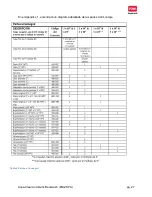
Страница 3: ...mbers ALT227 ALT227 2 either AC or DC B2x2350S551DSPBZVI B3x3350S551DSPBZVI B2x2350S554RCPBZVI B3x3350S554RCPBZVI n a ACK 3F ACK HYD1 ACK HYD1 1 either AC or DC B EXFP111002DP B EXFP111002DP B EXFP211002DP B EXFP211002DP Table 1 ACX 118 12VDCL ACX 124 12VDCL ACX 130 12VDCL ACX 136 12VDCL ACX 118 24VAC ACX 124 24VAC ACX 130 24VAC ACX 136 24VAC Aqua Clear Expansion Filter Qty 1 x 18 1 x 24 1 x 30 1 ...

Страница 4: ...stic 8mm Compression X 1 8 NPT 1 B FT98 1T Elbow Plastic 8mm Compression X 1 8 NPT 1 B FT28 EL Tee Plastic 8mm Compression 1 B FT98 T Bulkhead Adapters 2 2 AC BHA2 3 Fitting Kit Grooved Couplings 3 3 B DS V2030 Grooved Nipples 3 VG03PE Air Vent Cover Adapter 1 T 60403 The Aqua Clear Hydraulic Kit is included with the Filter station Part numbers are provided here for parts reference The Aqua Clear ...

Страница 5: ...a length of PVC pipe as practical and do not add unnecessary fittings and elbows this will prevent unnecessary pressure losses and improve efficiency Assembly of the Automatic Backwash valves 1 The 3 backwash valve model has grooved fittings The valve will need to be assembled to PVC grooved adapters included Basic assembly instructions for grooved fittings follow See Figure 2 Use a light coating ...

Страница 6: ...ting so that it equally straddles the grooved fitting on the valve and the grooved fitting on the adapter Clamp the Grooved fitting over the rubber gasket tightening the two bolts equally Some flexibility of this joint when complete is normal it is one of the advantages of a grooved fitting connection Hydraulic Control Filter Assembly See Figure 3 for detail on construction of Hydraulic Control Fi...

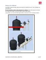
Страница 7: ... installation of all three manifolds see Figure 4 It is Very Important to support manifolds to prevent stresses to bulkhead fittings on filters Excessive stress can lead to failure of the filter A chart showing the basic recommended fittings and pipe lengths is in Table 4 Figure 4 Manifold Clearance Recommendation ...

Страница 8: ...Aqua Clear Automatic Backwash ENG SPA pg 8 A detailed assembly diagram for these parts is in the appendix Table 4 Parts toSource Locally ...

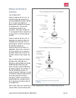
Страница 9: ...on the 8 closure on top of the filter The Air Vent can then be threaded onto this adapter Note This fitting is reverse thread so to tighten twist the nut counterclockwise There is a plastic air relief tube item 9 on the Replacement Parts diagram of the Filter Manual inside the filter attached to the Lower Piping Assembly it has a small screen filter on the upper end This tube is not attached to an...

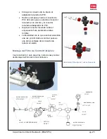
Страница 10: ...Aqua Clear Automatic Backwash ENG SPA pg 10 Connection of the Hydraulic Command Tubing Figure 7 Hydraulic Command Tube Connections Figure 6 ...

Страница 11: ... water used to control the valves is clean of debris This filter will become clogged over time and should be cleaned Closing the ball valve upstream of the filter will allow you to clean the filter even when the system is in operation Cleaning this filter should be a routine maintenance check and a troubleshooting step any time the backwash is not occurring as it should Operation of the Automatic ...

Страница 12: ...of the number of backwashes that have occurred between resets enabling the operator to evaluate the operation of the system over time Getting Started There are two stages to programming Steps 1 4 of this section assign values to commonly manipulated settings how long when and how frequently to backwash as well as some readouts from the controller on how many times the filter has backwashed Steps 5...

Страница 13: ... of the pressure differential that will initiate a flushing cycle Typical setting is 5 7 psi 3 The Flush Mode This sets the method by which the controller will trigger a backwash cycle The typical setting is By Time In this setting both the time and the pressure differential can trigger a backwash cycle if the PD sensor calls for a backwash before the timer does a backwash will occur and the timer...

Страница 14: ...oding or washout conditions where the backwash water exits and so a limit to the number of consecutive backwash cycles commanded by the PD sensor is set in this field If the filter enters into an endless loop of consecutive backwash cycles called for by the PD sensor when the limit set in this field is reached the PD sensor will be ignored and the filter will be triggered only by the timer When th...

Страница 15: ...reconnected after passing through this program step This will conclude the programming of the controller and it is ready to use If you want to revisit any of the settings simply cycle through them at this point If you wish to change setting 1 4 briefly press the ENTER key If you wish to re visit steps 5 13 press and hold the ENTER key for at least 3 seconds Manual Backwashing A flushing sequence c...

Страница 16: ...d be attached to the common terminal C as shown in Figure 11 The red wires should be attached as shown to terminals Out A and Out B respectively AC models The solenoid wires will be the same color One wire from each solenoid should be attached to the common terminal C and the other wires from each solenoid connected to terminals Out A and Out B see Figure 12 Figure 12 Wiring for AC Solenoid Figure...

Страница 17: ...ttery indication When the battery voltage drops to the first level the low battery sign will appear on the screen When the battery voltage drops further to the second level all outputs will shut down and the screen will be cleared leaving only the low battery icon The DC model must always be used with 12v DC Latching solenoid valves AC Model The AC model is connected by a transformer to an externa...

Страница 18: ...Aqua Clear Automatic Backwash ENG SPA pg 18 Figure 14 Finished Assembly ...

Страница 19: ...Aqua Clear Automatic Backwash ENG SPA pg 19 Appendix 1 Manifold Construction Detail Figure 15 ...

Страница 20: ...0 Aqua Clear Filtros de Arena de Fibra de Vidrio Anexo a la Guía de Instalación y al Manual de Usuario Montaje del Filtro de Retrolavado Automático Véase la Guía de Instalación y el Manual de Usuario para obtener las Instrucciones de Seguridad ...

Страница 21: ...24 Montaje del Filtro de Control Hidráulico 25 Montaje de los Múltiples 26 Montaje de Válvulas de Aire Vacío 28 Conexión de Tubería de Comando Hidráulico 29 Funcionamiento de Filtros Automáticos 30 Programación del Controlador de Retrolavado Automático 31 Diagrama de Cableado del Controlador 35 Apéndice 1 Construcción Detallada del Múltiple 38 ...

Страница 22: ...o del Sistema Por favor verifique de inmediato que ha recibido todas las piezas del sistema Para sistemas con dos filtros consulte la Tabla 1 Para sistemas de expansión de un filtro consulte la tabla 2 Los sistemas pueden contener paquetes para verificar el contenido detallado consulte la Tabla 3 Tabla 1 Tabla 2 ...

Страница 23: ... 8MMHYD 10 Disco de Filtro 3 4 1 ALGD75150 L Válcula de Escape 2 ARV BBK1 Buje de Reducción 1 4 x 1 8 Latón 2 28 102 Tee Plástico Compresión 8 mm x 1 8 NPT 1 B FT98 1T Codo Plástico Compresión 8 mm x 1 8 NPT 1 B FT28 EL Tee Plástico Compresión 8 mm 1 B FT98 T Bridas Roscadas 2 2 AC BHA2 Kit de Conectores 3 El Kit Hidráulico de Aqua Clear viene incluido con la estación del Filtro el Número de Parte...

Страница 24: ... fin de mantener la presión adecuada mejorando así la eficiencia del filtro Ilustración 1 Montaje de las Válvulas de Retrolavado Automáticas 1 El modelo de la válvula de retrolavado de 3 cuenta con tubería ranurada La válvula debe ser ensamblada a los adaptadores ranurados de PVC los cuales vienen incluidos Vea la ilustración 2 y siga las instrucciones para el Montaje de Tubería Ranurada Utilice u...

Страница 25: ...ambos tornillos La flexibilidad con la que cuenta el ensamble una vez ya terminado es normal pues es una de las ventajas de la conexión de tubería ranurada Montaje del Filtro de Control Hidráulico Vea la ilustración 3 para seguir las instrucciones precisas del Montaje del Filtro de Control Hidráulico Ilustración 2 Montaje de Tubería Ranurada BUJE DE REDUCCIÓN TEE 1 8 NPT x COMPRESIÓN 8 MM FILTRO Y...

Страница 26: ...e los 3 tres múltiples vea la ilustración 4 Es muy importante reforzar adecuadamente los múltiples para evitar el exceso de tensión en la bridas de los filtros ya que esto puede resultar al fallo del filtro Vea la Tabla 4 en la cual encontrará sugerencias de conectores así como longitudes de tubería Ilustración 4 Montaje de los Múltiples ...

Страница 27: ...Aqua Clear Automatic Backwash ENG SPA pg 27 En el Apéndice 1 encontrará un diagrama detallado de las partes del montaje Tabla 4 Partes a Conseguir ...

Страница 28: ...e vacío puede ser posteriormente enroscada en el adaptador Nota Este conector es de rosca inversa por lo que para ajustarse debe torcer la tuerca en sentido contrario a las manijas del reloj Hay un tubo de plástico por donde escapa el aire pieza 9 en el Diagrama de Reemplazo de Piezas del Manual del Filtro que está dentro del filtro adjunto al Montaje de Tubería Inferior el cual tiene un filtro de...

Страница 29: ...ando Hidráulico Ilustración 7 Conexión de Tubería de Comando Hidráulico Ilustración 6 Al ambiente Conectar al Puerto 1 en Válvulas de Lavado CONTROLADOR ALTO BAJO Válvula de Lavado 2 Válvula de Lavado 1 MANÓMETRO VÁLVULA BOLA FILTRO ENTRADA DE MÚLTIPLE SALIDA DE MÚLTIPLE ...

Страница 30: ... ascendiente del filtro permitirá limpiar el filtro incluso cuando el sistema está en funcionamiento La limpieza del filtro debe ser parte de una rutina de mantenimiento incluyendo la detección y resolución de problemas con el filtro en caso de que se presenten Funcionamiento de los Filtros Automáticos La imagen superior de la ilustración 8 muestra el funcionamiento de los filtros durante el modo ...

Страница 31: ...también realiza un seguimiento del número de ciclos de retrolavado que han ocurrido entre reinicios permitiendo al usuario evaluar el funcionamiento del sistema Inicio de la Programación Hay dos etapas durante el proceso de programación Los Pasos 1 al 4 de esta sección dan instrucciones en asignar valores que se ajustan frecuentemente cuánto tiempo cuándo y con qué frecuencia se realizará el ciclo...

Страница 32: ... Presión DP Este establece el valor del diferencial de presión en la que iniciará un ciclo de lavado Generalmente el ajuste es de 5 7 psi 3 El Modo de Lavado Esto establece el método por el cual el controlador comenzará un ciclo de retrolavado Generalmente la configuración es Por tiempo En este contexto tanto el tiempo como el diferencial de presión pueden comenzar al ciclo de retrolavado si el se...

Страница 33: ...iclos de lavado consecutivos Esto podría crear que se derrame el exceso de agua por lo que se debe establecer un número de ciclos consecutivos de retrolavado comandados por el sensor de DP En caso de que el filtro comience un bucle sin fin de ciclos de lavado consecutivos comandado por el sensor DP y una vez que el límite establecido haya sido alcanzado el sensor DP será rechazado y el filtro será...

Страница 34: ...rograma Esto concluye la programación del controlador el cual se encuentra listo para su uso Si desea volver a cualquiera de las funciones simplemente revise cada una de ellas De igual forma si desea volver a cualquier Configuración desplace y revise cada una Si desea realizar cambios en la configuración de los pasos 1 4 pulse brevemente la tecla ENTER y para realizar cambios en los pasos 5 13 pul...

Страница 35: ...erminal común C como los muestra la ilustración 11 Los cables color rojo deben unirse como lo muestran las terminales de salida A y B respectivamente Modelos AC Los cables de la bobina serán del mismo color Un solo cable de cada bobina debe ser unido a la terminal común C y los otros cables de cada bobina deben ser conectados a las terminales de salida A y B como lo muestra la ilustración 12 Ilust...

Страница 36: ...voltaje de la batería desciende hasta el primer nivel la señal de batería baja aparecerá en la pantalla Cuando el voltaje de la batería desciende por debajo del segundo nivel todas las salidas se apagarán mientras que en la pantalla permanecerá solo el icono de batería baja El modelo DC siempre se debe utilizar con válvulas bobinas de tipo Latching 12v DC Modelo AC El modelo AC está conectado por ...

Страница 37: ...Aqua Clear Automatic Backwash ENG SPA pg 37 Ilustración 14 Montaje Final ...

Страница 38: ...Aqua Clear Automatic Backwash ENG SPA pg 38 Apéndice 1 Construcción Detallada de Múltiple ...

Страница 39: ...tomatic Backwash ENG SPA pg 39 The Toro Company Micro Irrigation Business 1588 N Marshall Avenue El Cajon CA 92020 1523 USA Tel 1 800 333 8125 or 1 619 562 2950 Fax 1 800 892 1822 or 1 619 258 9973 Toro com ALT 227 ...

Отзывы: