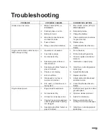
Toro 71202 Скачать руководство пользователя страница 45

43

Troubleshooting

PROBLEM

POSSIBLE CAUSES

CORRECTIVE ACTION

Starter does not crank

1.

Blade control (PTO) is
ENGAGED.

1.

Move blade control (PTO) to
DISENGAGED.

2.

Parking brake is not on.

2.

Set parking brake.

3.

Battery is dead.

3.

Charge the battery.

4.

Electrical connections are
corroded or loose.

4.

Check electrical connections
for good contact.

5.

Fuse is blown.

5.

Replace fuse.

6.

Relay or switch is defective.

6.

Contact Authorized Service
Dealer.

Engine will not start, starts hard, or
f il

k

i

1.

Operator is not seated.

1.

Sit on the seat.

g

,

,

fails to keep running.

2.

Fuel tank is empty.

2.

Fill fuel tank with gasoline.

3.

Air cleaner is dirty.

3.

Clean or replace air cleaner
element.

4.

Spark plug wire is loose or
disconnected.

4.

Install wire on spark plug.

5.

Spark plug is pitted, fouled, or
gap is incorrect.

5.

Install new, correctly gapped
spark plug.

6.

Choke is not closing.

6.

Adjust throttle cable.

7.

Dirt in fuel filter.

7.

Replace fuel filter.

8.

Idle speed is too low or
mixture is incorrect.

8.

Adjust carburetor idle speed
and idle mixture.

9.

Dirt, water, or stale fuel is in
fuel system.

9.

Contact Authorized Service
Dealer.

Engine loses power.

1.

Engine load is excessive.

1.

Shift into lower gear to reduce
ground speed.

2.

Air cleaner is dirty.

2.

Clean air cleaner element.

3.

Oil level in crankcase is low.

3.

Add oil to crankcase.

4.

Cooling fins and air passages
under engine blower housing
are plugged.

4.

Remove obstruction from
cooling fins and air passages.

5.

Spark plug is pitted, fouled, or
gap is incorrect.

5.

Install new, correctly gapped
spark plug.

Содержание 71202

Страница 1: ...fully It contains information about your safety and the safety of others Also become familiar with the controls and their proper use before you operate the product FORM NO 3315 999EN Rev A Wheel Horse...

Страница 2: ...mage to the product Although Toro designs produces and markets safe state of the art products you are responsible for using the product properly and safely You are also responsible for training person...

Страница 3: ...g the Engine 12 The Safety System 13 Driving Forward or Backward 14 Selecting Ground Speeds 14 Stopping the Machine 14 Side Discharge or Mulch Grass 15 Installing the Discharge Cover 15 Tips for Mowin...

Страница 4: ...on 1 Read understand and follow all instructions in the operator s manual and on the machine before starting 2 Allow only responsible adults who are familiar with the instructions to operate the machi...

Страница 5: ...uts or bumps as uneven terrain could overturn the machine Tall grass can hide obstacles Use slow speed Choose a low gear so that you will not have to stop or shift while on the slope Follow the manufa...

Страница 6: ...ng Do not smoke C Never refuel the machine indoors D Never store the machine or fuel container inside where there is an open flame such as near a water heater or furnace 3 Never run a machine inside a...

Страница 7: ...Safety 5 Slope Chart Read all safety instructions on pages 2 4...

Страница 8: ...6...

Страница 9: ...ty 7 International Symbols ENGINE STOP ENGINE RUN ENGINE START START SWITCH MECHANISM ON START OFF STOP HEADLIGHTS MAIN BEAM PTO ENGAGE DISENGAGE PARKING BRAKE CHOKE FAST CONTINUOUSLY VARIABLE LINEAR...

Страница 10: ...fumes may be ignited by a spark Store gasoline in an approved container and keep it out of the reach of children Never buy more than a 30 day supply of gasoline Stabilizer Conditioner Toro Stabilizer...

Страница 11: ...brake lever 9 Tilt button selected models 10 Throttle lever 11 Hood opening 1 2 3 4 5 6 7 8 9 10 11 Parking Brake Always set the parking brake when you stop the machine or leave it unattended Setting...

Страница 12: ...ng the Tilt Steering Wheel On select models the steering wheel tilts up and down Position the steering wheel where you have the best control of the machine and are most comfortable 1 Push in on the ti...

Страница 13: ...the desired cutting height 1 The cutting height may be set in one of seven positions from approximately 1 to 4 inches 25 to 102 mm 2 Pull on the height of cut lever deck lift and move it to the desire...

Страница 14: ...m may not require step 5 6 Turn the ignition key clockwise and hold it in the START position Fig 11 When the engine starts release the key IMPORTANT If the engine does not start after 30 seconds of co...

Страница 15: ...ake pedal is released or the blade is ENGAGED Testing the Safety System Test the safety system before you use the machine each time If the safety system does not operate as described below have an Aut...

Страница 16: ...to or out of reverse Always start the machine in motion by depressing the clutch brake pedal and shifting into the desired speed Once the machine is in motion you can shift into any forward speed with...

Страница 17: ...he mower has a hinged grass deflector that disperses clippings to the side and down toward the turf 2 To mulch grass clippings you must install the discharge cover optional on some models into the ope...

Страница 18: ...growth rate slows in mid summer mow less frequently If you cannot mow for an extended period first mow at a high cutting height then mow again 2 days later at a lower height setting Avoid Cutting Too...

Страница 19: ...wear cracks X Gasoline drain X Engine clean outside X X Mower Housing clean X X X Chipped Surfaces paint X Battery check electrolyte X X X X X Battery charge disconnect cables X Fuel Filter replace X...

Страница 20: ...age the blade control PTO shift into neutral set the parking brake and turn the ignition key to OFF to stop the engine 2 Clean the grease fittings with a rag Make sure to scrape any paint off the fron...

Страница 21: ...key to OFF to stop the engine 2 If the rear wheels lock and skid when you push the tractor forward no adjustment is required An adjustment is required if the wheels turn and do not lock refer to Adju...

Страница 22: ...Maintenance 20 Wiring Diagram C 1301...

Страница 23: ...turn counterclockwise and remove it from the reflector Fig 18 4 Push and rotate the bulb counterclockwise until it stops approx 1 4 turn and remove bulb from the bulb holder Fig 19 Figure 18 1 Bulb h...

Страница 24: ...d long vent tube from the chassis Fig 21 Figure 20 1 Negative cable black 2 Rubber cover 3 Positive cable red 4 Battery box 5 Bolt and wing nut 1 2 3 4 5 Installing the Battery 1 Put the battery into...

Страница 25: ...overfill the battery because electrolyte sulfuric acid can cause severe corrosion and damage to the chassis 4 Screw the filler caps onto the battery Charging the Battery IMPORTANT Always keep the bat...

Страница 26: ...ling into the engine and potentially causing damage 4 Remove the spark plug and metal washer Figure 23 1 Spark plug wire 2 Spark plug 2 1 Checking the Spark Plug 1 Look at the center of the spark plug...

Страница 27: ...uel line toward the fuel tank Fig 25 4 Pull the fuel line off the filter Fig 25 and allow gasoline to drain into a gas can or drain pan Note Now is the best time to install a new fuel filter because t...

Страница 28: ...ver must snap into a notch B With the throttle in the FAST position index holes in the governor control lever and the governor plate must align Fig 26 If they do not align refer to step 4 for adjustme...

Страница 29: ...until it just closes Do not force tighten the idle mixture screw because the carburetor could be damaged B Open the idle mixture screw Fig 27 one turn counterclockwise This setting allows you to start...

Страница 30: ...nts 1 Disengage the blade control PTO shift into neutral set the parking brake and turn the ignition key to OFF to stop the engine 2 Open the hood 3 Clean around the air cleaner to prevent dirt from g...

Страница 31: ...bber seal IMPORTANT Never clean the paper element with pressurized air or liquids such as solvent gas or kerosene Replace the paper element if it is damaged defective or cannot be cleaned thoroughly F...

Страница 32: ...he metal end clean Fig 33 5 Screw the oil dipstick fully onto the filler tube Fig 33 Unscrew the dipstick again and look at the metal end If oil level is low slowly pour only enough oil into the fille...

Страница 33: ...6 Slowly pour approximately 80 of the specified amount of oil into the filler tube Fig 33 Now check the oil level refer to Checking Oil Level page 30 steps 4 5 Figure 34 1 Oil drain plug 2 Oil dipstic...

Страница 34: ...ge 34 2 Inspect the cutting edges Fig 35 If the edges are not sharp or have nicks remove the blade s and sharpen them refer to Sharpening the Blade s page 33 3 Inspect the blade s especially the curve...

Страница 35: ...ancer Fig 38 If the blade stays in a horizontal position the blade is balanced and can be used If the blade is not balanced file some metal off the back side of the blade Repeat this procedure until t...

Страница 36: ...el Figure 39 1 Spring 2 Bolt 3 Spring tool 1 2 3 POTENTIAL HAZARD The height of cut lever deck lift is spring tensioned WHAT CAN HAPPEN When the mower is being removed this spring loaded mechanism cou...

Страница 37: ...ut of the mower mount Repeat this step on the opposite side of the mower IMPORTANT Tape or tie the long rods against the chassis to protect them from damage when you remove the mower 10 Remove the mow...

Страница 38: ...1 8 3 175 mm between the belt guide and the edge of the pulley to keep the belt on the pulley during operation If the space is more than 1 8 3 175 mm adjust the belt guide s and tighten them securely...

Страница 39: ...er guides 1 2 3 10 Move the height of cut lever deck lift into the D notch to make it easier to install the height of cut lift assist spring 11 Hook the height of cut lift assist spring onto the retai...

Страница 40: ...leys Installing the Blade Drive Belt 1 Install the new belt around the blade pulleys and under the belt guide on the idler pulley 2 Position the idler pulley belt guide so it points toward the left 90...

Страница 41: ...ch 4 Carefully rotate blade s side to side Fig 49 Measure between the outside cutting edges and the flat surface Fig 49 If both measurements are not within 3 16 4 762mm an adjustment is required refer...

Страница 42: ...Side Mower Leveling page 39 4 Move the height of cut lever deck lift into the C notch 5 Check the front to rear slope by measuring between the bottom of the mower front center and rear center and the...

Страница 43: ...check the front to rear slope again Continue to adjust the rods one turn at a time until the front of the mower is 1 8 to 3 8 3 175 mm to 9 525 mm lower than the rear of the mower Note To raise the f...

Страница 44: ...ully refer to Battery page 22 Do not connect the battery cables to the battery posts during storage IMPORTANT The battery must be fully charged to prevent it from freezing and being damaged at tempera...

Страница 45: ...ent 4 Spark plug wire is loose or disconnected 4 Install wire on spark plug 5 Spark plug is pitted fouled or gap is incorrect 5 Install new correctly gapped spark plug 6 Choke is not closing 6 Adjust...

Страница 46: ...de mounting bolt 3 Engine mounting bolts are loose 3 Tighten engine mounting bolts 4 Loose engine pulley idler pulley or blade pulley 4 Tighten the appropriate pulley 5 Engine pulley is damaged 5 Cont...

Отзывы: