Important:
Do not
install the remaining
threaded fitting on the end of the rinse tube at
this time.
G005794
5
4
1
3
2
Figure 17
1.
Bulkhead assembly
4.
O–ring, small, black
2.
Rinse nozzle and tube
assembly
5.
Retainer nut, large
3.
Main tank surface
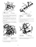
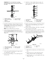
5. Install the small, black O-ring and large retainer nut,
which you previously removed, over the top of the
un-threaded
end of the rinse tube protruding from
the bulkhead fitting (Figure 17).
Note:
Do not tighten the nut at this time.
6. Adjust the rinse nozzle assembly position so the
top of the
un-threaded
end of the tube stands
approximately 10 cm (4 inches) from the tank surface
(Figure 18).
G005795
2
4
3
1
5
Figure 18
1.
Rinse nozzle assembly
4.
Retainer nut, large
2.
Un–threaded end of tube
5.
10 cm (4 inches)
3.
Tank surface
7. Set the tube height by tightening the larger retainer
nut installed above (Figure 18).
8. Snap the threaded fitting over the remaining end of
the rinse tube.
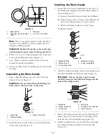
9. Install the 1/2 inch middle fitting into place and
secure it with the medium retainer nut from loose
parts (Figure 19).
G005796
1
2
3
4
5
6
Figure 19
1.
Threaded fitting
4.
Retainer nut, medium
2.
Rinse tube
5.
O-ring, small clear
3.
1/2 inch middle fitting
6.
60 degree elbow
10. Install a small, clear O-ring into the 60 degree elbow
fitting and then install the fitting onto 1/2 inch
middle fitting.
11. Position the elbow fitting so that it faces to the right
and to the rear of the machine.
12. Use the following procedure to assemble the rinse
nozzle hose as shown in (Figure 20). Locate a small,
clear O-ring, the hose barb, small retainer nut, metal
clamp, and rinse nozzle hose in loose parts.
G005797
1
2
3
4
5
Figure 20
1.
O-ring, small clear
4.
Hose clamp
2.
Hose barb
5.
Hose
3.
Retainer nut, small
A. Slide the hose clamp, loose, over the rinse nozzle
hose.
B. Install the O-ring over the barbed end of the
fitting and push it flush to the fitting flange.
C. Install the plastic nut over the barbed end of the
fitting and O-ring.
10

