background image

Tap and hold the bottom of the switch to override
and lock out (disable) the foot switch. The LED
illuminates in the hour meter/tine engagement
display. Use this feature when transporting the
aerator.

To unlock, tap and hold the top of the multi-function
switch until the LED light disappears.

Note:

The lockout feature is engaged each time the

engine is switched off.

Multi-Function Switch

The multi-function switch is located to the left of the
hour meter/tine engagement display.

This switch allows the operator to do the following:

increase or decrease the depth of aeration plug

lock or unlock the tine depth setting

reset maintenance service reminder screens

Smart Controller/Electronic Depth
Control

Hour Meter/Tine Engagement Display

Located to the left of the ignition switch on the control
console.

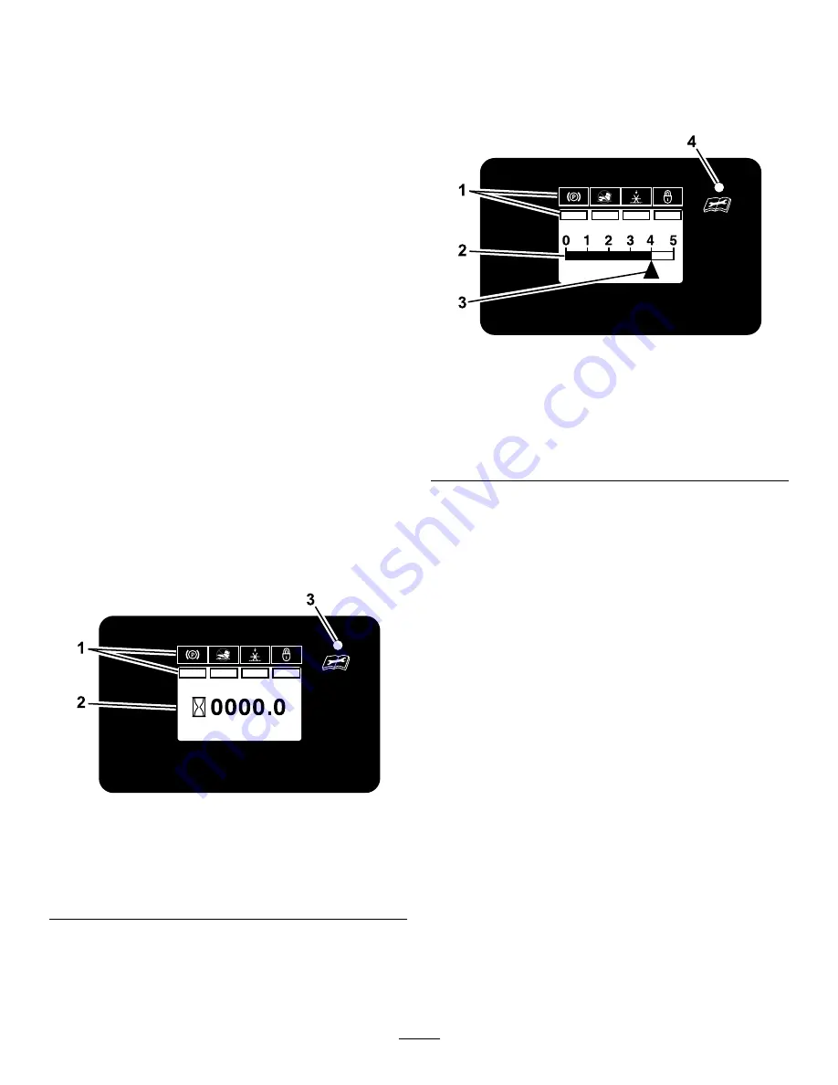
The hour meter monitors and displays engine
hours.

g211730

Figure 10

Hour Meter Display

1.

LCD Indicators/Information screen

2.

Hour display

3.

LED status light

Hours are displayed when the key is off or when
the machine is running. Hours are not displayed
when the machine is aerating.

Note:

The LCD indicator appears in the parking

brake setting when it meets the safe to start mode
(parking brake engaged).

The tine engagement display monitors and
displays the electronic tine depth setting.

g211731

Figure 11

Tine Engagement Display

1.

LCD Indicators/Information screen

2.

Tine depth status bar

3.

Tine depth setting indicator

4.

LED status light

There are two ways to activate the display.

1.

Tap the multi-function switch either up or down
to display the tine engagement meter.

2.

Step on the tine ground engagement foot switch.

A higher number on the status bar increases the
length of the aeration plug and a lower number
decreases it.

Note:

If the plug length is not the desired length, you

may need to adjust the machine to accommodate
for your weight; refer to the

Adjusting the Operator

Weight Control Valve (page 23)

.

LED Status Lights

Located on the right side of the hour meter/tine
engagement display.

The LED is multi-colored to indicate the system status
and is located on the right side of the panel.

Solid Green

— indicates normal operating activity

Blinking Red

— indicates that a fault is active

Solid Red

— indicates that maintenance is

required

17


Содержание 39514

Страница 1: ...Form No 3421 850 Rev C 24in Stand On Aerator Model No 39514 Serial No 400000000 and Up Register at www Toro com Original Instructions EN 3421 850 C ...

Страница 2: ...maintain your product properly and to avoid injury and product damage You are responsible for operating the product properly and safely You may contact Toro directly at www Toro com for product safety and operation training materials accessory information help finding a dealer or to register your product Whenever you need service genuine Toro parts or additional information contact an Authorized S...

Страница 3: ...36 Electrical System Maintenance 36 Jump Starting the Machine 36 Servicing the Battery 37 Drive System Maintenance 38 Checking the Drive Tire Air Pressure 38 Checking the Wheel Hub Bolts 38 Checking the Torque of the Wheel Lug Nuts 38 Checking the Condition of the Chains 39 Checking the Sprocket Condition 39 Maintaining the Chain 39 Checking the Torque of the Transmission Output Shaft Nut 39 Adjus...

Страница 4: ...s are from ANSI B71 4 2017 Training Read and understand the contents of this Operator s Manual before starting the engine Become familiar with the safe operation of the equipment operator controls and safety signs All operators and mechanics should be trained The owner is responsible for training the users Never let children or untrained people operate or service the equipment Local regulations ma...

Страница 5: ...ngine Start the engine only from the operator s position Ensure that you have good footing while using this machine especially when backing up Reduced footing could cause slipping Slow down and use extra care on hillsides Be sure to travel side to side on hillsides Turf conditions can affect the stability of the machine Use caution while operating near drop offs Slow down and use caution when maki...

Страница 6: ...ed Replace all worn or damaged decals Aerator Safety The following list contains safety information specific to Toro products and other safety information you must know General Operation Check carefully for overhead clearances i e branches doorways electrical wires etc before operating under any objects and do not contact them Use caution when you are riding on the platform and driving the machine...

Страница 7: ...ve or mark obstacles such as ditches holes ruts bumps rocks or other hidden hazards Tall grass can hide obstacles Uneven terrain could overturn the machine Use extra care while operating with accessories or attachments These can change the stability of the machine and cause a loss of control Follow directions for counter weights If you lose control of the machine step off and away from the directi...

Страница 8: ...g do not touch the hot surface 2 Read the Operator s Manual decal117 2718 117 2718 decal120 9570 120 9570 1 Warning stay away from moving parts keep all guards and shields in place decal121 6150 121 6150 1 Cutting hazard of hand and foot stay away from moving parts decal121 6161 121 6161 1 Entanglement hazard belt stay away from moving parts keep all guards in place decal121 6163 121 6163 1 Press ...

Страница 9: ...the chain tension twice every 8 hours 7 Check the tire pressure 23 psi twice every 50 hours 3 See the engine owner s manual for service 8 Check the hydraulic oil level twice Use only recommended hydraulic fluid every 50 hours 4 Check the auxiliary pump drive belt tension every 50 hours 9 Check the auxiliary hydraulic tank Use only AW 32 hydraulic fluid every 50 hours 5 Grease the front caster whee...

Страница 10: ...he Operator s Manual before performing maintenance 3 Tines down STOP LB KG 135 2013 2 1 3 4 5 6 7 8 9 10 decal135 2013 1 135 2013 1 Operator weight adjustment 5 Throttle slow 9 Parking brake engage 2 Increase 6 Engine on 10 Parking brake release 3 Decrease 7 Engine start 4 Throttle fast 8 Engine off 10 ...

Страница 11: ...l guards in place 14 Tipping hazard Do not turn sharply while traveling fast slow down and turn gradually 5 Wheels and tines rotate when moving forward 10 Warning Do not operate the machine unless you are trained 15 Tipping hazard Do not use split ramps use full width ramps to load a machine for transport decal135 2016 135 2016 1 Electronic tine depth decrease 2 Electronic tine depth increase 3 Pr...

Страница 12: ...ck the air pressure in the drive tires and adjust the pressure as needed refer to Checking the Drive Tire Air Pressure page 38 Note You do not adjust air pressure for the semi pneumatic caster tires 2 Servicing the Engine Oil No Parts Required Procedure The engine is shipped with oil check the engine oil level and if necessary add oil to the specified level refer to Engine Oil Specification page 3...

Страница 13: ...luid Specification page 45 and Checking the Transmission Fluid Level page 45 5 Check the Auxiliary Hydraulic Fluid Level No Parts Required Procedure The auxiliary hydraulic reservoir is shipped with hydraulic fluid Check the hydraulic reservoir fluid level and if necessary add fluid to the specified level refer to Auxiliary Hydraulic Fluid Specification page 43 and Checking the Auxiliary Hydraulic...

Страница 14: ...trol lever 10 Parking brake handle 5 Front reference bar 11 Ignition switch 6 Throttle Motion Control Levers The motion control levers are located on each side of the top console and control the forward and reverse motion of the machine Move the levers forward or backward to control the drive wheel on the same side forward or reverse respectively The wheel speed is proportional to the amount you m...

Страница 15: ...itions OFF ON and START Figure 7 g008610 Figure 7 1 OFF 3 START 2 ON Parking Brake Handle The parking brake handle is located on the control console to the right of the key switch Figure 5 Note The brake handle engages a parking brake in each of the transmissions To engage the parking brake pull the handle back toward you To release the parking brake push the handle all the way forward away from y...

Страница 16: ...ine Operator Weight Adjustment Control The operator weight adjustment valve is located at the left side of the control console Figure 9 g249578 Figure 9 1 Operator weight adjustment control Use the operator weight adjustment valve to help compensate for the weight of the operator so that the machine achieves the correct aerating pressure plug length and to help maximize lateral machine stability N...

Страница 17: ...s running Hours are not displayed when the machine is aerating Note The LCD indicator appears in the parking brake setting when it meets the safe to start mode parking brake engaged The tine engagement display monitors and displays the electronic tine depth setting g211731 Figure 11 Tine Engagement Display 1 LCD Indicators Information screen 2 Tine depth status bar 3 Tine depth setting indicator 4...

Страница 18: ...r 2 seconds The LED status light changes from red to orange to green The first screen displays the firmware version g212116 Figure 12 The second screen displays the aeration hours to the tenth of an hour g212114 Figure 13 The third screen displays the battery voltage to the tenth of a volt g212115 Figure 14 The fourth screen displays the hours until the engine oil maintenance is required If the se...

Страница 19: ...red There are two maintenance reminders 1 Service Engine The engine oil service reminder counts down from the initial break in service interval of 5 engine hours and then counts down from 100 hours for each service interval thereafter g030960 Figure 17 2 Service Transmission The transmission oil maintenance reminder counts down from the initial break in service interval of 250 engine hours and the...

Страница 20: ...ys in the lower left corner of the screen The LED flashes a red light g030971 Figure 20 1 Number 6 displays Valve Solenoid Overcurrent Error If an overcurrent event occurs the number 2 displays in the lower left corner of the screen Check the valve solenoid and inspect it for damage and wear The LED flashes a red light g030972 Figure 21 1 Number 2 displays Valve Solenoid Connection Error The syste...

Страница 21: ...ides of the machine from the normal operating position Adding Fuel DANGER In certain conditions fuel is extremely flammable and highly explosive A fire or explosion from fuel can burn you and others and can damage property Fill the fuel tank outdoors in an open area and when the engine is cold Wipe up any fuel that spills Do not fill the fuel tank completely full Add fuel to the fuel tank until th...

Страница 22: ... 7 L 1 9 US gallons 1 Clean around the fuel tank cap 2 Remove the cap from the tank 3 Fill the fuel tank with fuel to within 6 to 13 mm 1 4 to 1 2 inch from the top of the tank Do not fill into the filler neck Important Do not fill the tank more than 6 mm 1 4 inch from the top of the tank because the fuel must have room to expand 4 Install the fuel tank cap and wipe up any spilled fuel Opening and...

Страница 23: ...Tine Depth Setting 1 Stop the machine and engage the parking brake 2 Press the multi function switch to activate the display 3 Cycle the key switch between the RUN position and the OFF position 5 times The tine depth setting indicator triangle on the display will begin to flash 4 Tap the multi function switch up or down to set the aeration depth Tap the bottom of the multi function switch to lower...

Страница 24: ...ring the machine to a full stop 2 Lift your foot off of the tine ground engagement foot switch control to raise the tines 3 Activate the tine engagement foot switch lockout 4 Place the throttle midway between the SLOW and FAST positions 5 Allow the engine to run for a minimum of 15 seconds then turn the ignition switch to the OFF position to shut off the engine 6 Engage the parking brake 7 Remove ...

Страница 25: ... the motion control lever toward the desired turn direction To make zero turns lift your foot off of the tine ground engagement foot switch to raise the tines The head will raise in half second Important Do not make a zero turn when the tines are in the down position 3 To stop position both motion control levers in the neutral operating position Positioning the Air Cleaner Cover for Cold or Warm A...

Страница 26: ...the machine to tip backward If loading on or near a slope position the trailer or truck so that it is on the down side of the slope and the ramps extends up the slope This minimizes the ramp angle The trailer or truck should be as level as possible Important Do not attempt to turn the machine while on the ramp you may lose control and drive off the side Avoid sudden acceleration when driving up a ...

Страница 27: ... a violation of state laws and the operator may be subject to traffic tickets and or fines Do not drive the machine on a public street or roadway WARNING Loading a machine on a trailer or truck increases the possibility of backward tip over Backward tip over could cause serious injury or death Use extreme caution when operating a machine on a ramp Use only a single full width ramp Do not use indiv...

Страница 28: ...e first and negative last Keep the machine guards shields and all safety devices in place and in safe working condition Frequently check for worn or deteriorating components and replace them with the manufacturer s recommended parts when necessary WARNING Removal or modification of original equipment parts and or accessories may alter the warranty controllability and safety of the machine Unauthor...

Страница 29: ...e ground drive hydraulic system by placing the motion control levers in neutral and shutting off the engine Safely relieve all pressure in the auxiliary hydraulic system by shutting off the engine turning the ignition switch to the ON position and pressing the tine ground engagement switch Once the tines have lowered to the ground release the tine ground engagement switch and turn the ignition swi...

Страница 30: ...ed bearings Every 50 hours Clean the foam pre cleaner more frequently in dusty conditions Check spark arrester if equipped Check the air pressure in the drive tires Check the condition and tension of the belts Check the transmission fluid level Every 80 hours Remove the engine shrouds and clean the cooling fins Every 100 hours Change the engine oil more often under severe conditions Every 160 hour...

Страница 31: ...ubricant 1 Shut off the engine wait for all moving parts to stop and remove the key Engage the parking brake 2 Lift the rear of the machine and support using jack stands or equivalent support CAUTION Raising the machine for service or maintenance relying solely on mechanical or hydraulic jacks could be dangerous The mechanical or hydraulic jacks may not be enough support or may malfunction allowin...

Страница 32: ... Interval Every 50 hours Clean the foam pre cleaner more frequently in dusty conditions Every 200 hours Replace the foam pre cleaner Every 300 hours Replace the paper air filter more frequently in dusty conditions Important Do not operate the engine without the air filter assembly extreme engine damage may occur 1 Release the latches on the cover for the air cleaner 2 Remove the cover and clean it...

Страница 33: ...gent oil API service SJ or later Engine Oil Capacity 1 7 L 1 8 US qt without the filter 1 5 L 1 6 US qt with the filter Oil viscosity Refer to the table below g023796 Figure 35 Checking the Engine Oil Level Service Interval Before each use or daily Important Do not operate the engine with the oil level below the Low or Add mark on the dipstick or over the Full mark 1 Move the machine to a level su...

Страница 34: ...y 2 Shut off the engine engage the parking brake remove the key and wait for all moving parts to stop before leaving the operating position 3 Change the engine oil as shown in Figure 37 Note Torque drain plug to 18 N m 13 ft lb g249685 Figure 37 4 Slowly pour approximately 80 of the specified oil into the filler tube and slowly add the additional oil to bring it to the Full mark Figure 38 g249684 ...

Страница 35: ...ut off the engine engage the parking brake remove the key and wait for all moving parts to stop before leaving the operating position 2 Remove the spark plug as shown in Figure 39 g027478 Figure 39 Checking the Spark Plug Important Do not clean the spark plug s Always replace the spark plug s when it has a black coating worn electrodes an oily film or cracks If you see light brown or gray on the i...

Страница 36: ...eak battery for terminal corrosion and clean it prior to jump starting Clean and tighten connections as necessary CAUTION Corrosion or loose connections can cause unwanted electrical voltage spikes at anytime during the jump starting procedure Do not attempt to jump start with loose or corroded battery terminals or damage to the engine may occur DANGER Jump starting a weak battery that is cracked ...

Страница 37: ...y produce explosive gases Battery gases can explode causing serious injury Keep sparks flames or cigarettes away from the battery Ventilate when charging or using the battery in an enclosed space Ensure that the venting path of the battery is always open once the battery is filled with acid Always shield your eyes and face from the battery DANGER Battery electrolyte contains sulfuric acid which is...

Страница 38: ...onnected connect the positive red cable to the positive battery terminal and slip the terminal cover over the positive terminal 5 Remove the screw washer and ground cable from the engine Connect the negative battery cable Note If time does not permit charging the battery or if charging equipment is not available connect the negative battery cables and run the vehicle continuously for 20 to 30 minu...

Страница 39: ...ngage the parking brake wait for all moving parts to stop and remove the key 2 Lift the rear of the machine and support using jack stands or equivalent support 3 Check the chains on each side of the idler sprocket at both sides of the machine for proper tension The chains should move up and down 6 to 12 mm 1 4 to 1 2 inch 4 To adjust the chain tension loosen the idler bolt and locknut and push up ...

Страница 40: ...rol Tracking If the machine travels or pulls to one side when the motion control levers are in the full forward position adjust the tracking 1 Push both control levers forward the same distance 2 Check if the machine pulls to one side If it does stop the machine and set the parking brake 3 Loosen the lock nuts on the right motion control linkage as viewed from the rear of the machine Push the righ...

Страница 41: ...ly an adjustment is required 1 Refer to Preparing for Maintenance page 31 2 Check the air pressure in the drive tires If needed adjust to the recommended inflation refer to Checking the Drive Tire Air Pressure page 38 3 Disengage the parking brake 4 Loosen the cable clamp on the brake cables under the console Figure 49 5 Adjust both cable conduits downward approximately 1 8 to 1 4 inch 3 to 6 mm g...

Страница 42: ...tment cover left 3 Loosen the 2 flange locknuts 3 8 inch securing the auxiliary pump to the mounting bracket Figure 51 g266181 Figure 51 1 Auxiliary pump drive belt 3 Flange locknuts 2 Auxiliary pump 4 Slide the pump outward Figure 51 in slots and torque the flange locknuts to 37 to 45 N m 27 to 33 ft lb When properly adjusted the belt should have 1 2 inch 1 3 cm of deflection with 3 pounds of for...

Страница 43: ... is embossed into the baffle of the reservoir Figure 52 g266183 g266182 Figure 52 1 Cap 3 Hot fluid level baffle 2 Auxiliary hydraulic reservoir 4 Cold fluid level baffle 5 If necessary add the specified hydraulic fluid to the reservoir until the fluid covers the FULL COLD fluid level on the baffle Figure 52 Note If the fluid is at ambient air temperature about 24 C 75 F fill only to the FULL COLD...

Страница 44: ...uid to the rubber seal of the new filter refer to Auxiliary Hydraulic Fluid Specification page 43 3 Turn the filter clockwise until rubber seal contacts the filter adapter then tighten the filter an additional 2 3 to 3 4 turn Figure 54 Adding Auxiliary Hydraulic Fluid 1 Remove the cap and check the hydraulic fluid level in the reservoir 2 Add the specified hydraulic fluid until the level reaches t...

Страница 45: ...portant Do not overtighten the expansion tank cap Changing the Hydraulic Transmission Filters and Fluid Service Interval After the first 100 hours Every 250 hours thereafter Important Do not change the hydraulic fluid except for what can be drained when changing filter and removing the drain plugs unless it is felt the oil has been contaminated or been extremely hot Changing the oil unnecessarily ...

Страница 46: ...freely CAUTION Raising the machine for service or maintenance relying solely on mechanical or hydraulic jacks could be dangerous The mechanical or hydraulic jacks may not be enough support or may malfunction allowing the machine to fall which could cause injury Do not rely solely on mechanical or hydraulic jacks for support Use adequate jack stands or equivalent support 6 Start the engine and move...

Страница 47: ... other debris from the tines 5 Inspect the tines for wear and damage Note Replace any tines that are worn or damaged 6 Align the holes in the rear cover panel to the holes in the chassis Figure 57 7 Secure the cover panel to the chassis with the 2 thumbscrews and 2 washers Figure 57 that you removed in step 3 and torque the bolts to 37 to 45 N m 27 to 33 in lb Adjusting the Tine Drive Chain 1 Shut...

Страница 48: ...by turning the bolt at the front of each spring clockwise will shorten the gap counter clockwise will lengthen the gap g233568 Figure 59 1 1 38 inch 35 mm Important The springs must be replaced it the gap is less than 1 13 inches 29 mm Always replace both return to up springs This prevents uneven loading and possible damage to the machine Chassis Maintenance Check for Loose Hardware Service Interv...

Страница 49: ...s Cleaning the Debris from the Machine Service Interval Before each use or daily 1 Shut off the engine engage the parking brake remove the key and wait for all moving parts to stop before leaving the operating position 2 Clean off any oil debris or grass buildup on the machine and aerator deck 3 Clean off any debris or grass under the chain guards around the fuel tank and around the engine and exh...

Страница 50: ...lly near the engine and hydrostatic drive 3 Service the air cleaner refer to Servicing the Air Cleaner page 32 4 Lubricate the machine refer to Lubrication page 31 5 Change the engine oil refer to Changing the Engine Oil page 34 6 Check and tighten all bolts nuts and screws Repair or replace any part that is damaged 7 Paint all scratched or bare metal surfaces Paint is available from your authoriz...

Страница 51: ...y dielectric grease and connect 7 A relay or switch is not functioning properly 7 Contact an Authorized Service Dealer 8 The spark plug is faulty 8 Clean adjust or replace the spark plug 9 The spark plug wire is not connected 9 Check the spark plug wire connection The engine does not start starts hard or fails to keep running 10 The ambient temperature is too low 10 Place the machine into a warmer...

Страница 52: ...w belt There is abnormal vibration 7 The chains are not properly tensioned 7 Check the drive wheel chain tension and the tine drive chain tension 1 There is a short in the wire harness 1 Contact an Authorized Service Dealer 2 The return to up springs are not properly adjusted 2 Adjust the return to up springs The tines do not raise 3 The return to up springs are damaged 3 Replace the return to up ...

Страница 53: ...Notes ...

Страница 54: ...Notes ...

Страница 55: ...Notes ...

Страница 56: ......

Отзывы: