background image

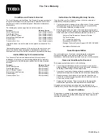
Federal Emission Control Warranty Statement

A Two-Year Limited Warranty

Your Warranty Rights and Obligations

The U.S. Environmental Protection Agency (EPA), The Toro Company, and
its affiliate, Toro Warranty Company, are pleased to explain the emission
control system warranty on your 2009 and later utility/lawn/garden
equipment engine. 2009 and later model year utility/lawn/garden
equipment engines must be designed, built and equipped, at the time
of sale, to meet the U.S. EPA regulations for small non-road engines.
The equipment engine must be free from defects in materials and
workmanship, which cause it to fail to conform with U.S. EPA standards,
for the first two years of engine use from the date of sale to the ultimate
purchaser. The Toro Company and its affiliate, Toro Warranty Company,
warrant the emission control system on your utility/lawn/garden equipment
engine for the period of time listed above, provided there has been no
abuse, neglect, or improper maintenance of your utility/lawn/garden
equipment engine.

Your emission control system may include parts such as the carburetor
or fuel injection system, the ignition system, and catalytic converter. Also
included may be fuel lines, fuel line fasteners, connectors, and other
emission-related assemblies.

Where a warrantable condition exists, The Toro Company and its affiliate,
Toro Warranty Company, promise to repair your engine at no cost to you,
including diagnosis, parts, and labor.

Manufacturer’s Warranty Coverage

The Toro Company and its affiliate, Toro Warranty Company, pursuant
to an agreement between them, jointly warrant the 2009 and later
utility/lawn/garden equipment engines for two years from the date of
delivery. If any emission-related part on your engine is defective in
materials or workmanship, we will repair or replace the part, free of charge.

Owner Responsibilities

As the engine owner, you are responsible for the performance of the
required maintenance listed in your

Operator's Manual

. We recommend

that you retain all receipts covering maintenance on your equipment, but
we cannot deny warranty solely for the lack of receipts or for your failure to
ensure the performance of all scheduled maintenance.

Any replacement part or service that is equivalent in performance and
durability may be used in non-warranty maintenance or repairs, and shall
not reduce our warranty obligation.

As the engine owner, you should be aware that we may deny you warranty
coverage if your engine or a part has failed due to abuse, neglect,
improper maintenance, or unapproved modifications or parts.

You are responsible for presenting your equipment engine to an Authorized
Service Dealer as soon as a problem exists. The warranty repairs should
be completed in a reasonable amount of time, not to exceed thirty (30)
days.

If you have any questions regarding your warranty rights and
responsibilities, contact us at:

Customer Care Department, Consumer Division
Toro Warranty Company
8111 Lyndale Avenue South
Bloomington, MN 55420-1196
Toll free at 800–348–2424 (U.S. customers)
Toll free at 800–544–5364 (Canadian customers)

Warranted Parts

The warranty period begins on the date the engine or equipment is
delivered to a retail purchaser. The Toro Company and its affiliate,
Toro Warranty Company, jointly warrant to the initial owner and each
subsequent purchaser that the engine is free from defects in materials and
workmanship, which cause the engine to fail to conform with applicable
regulations, for a period of two years.

Failures caused by abuse, neglect, or improper maintenance are not
covered. The use of add-on or modified parts can be grounds for
disallowing a warranty claim. We are not liable to cover failures of
warranted parts caused by the use of add-on or modified parts. We are
liable for damages to other engine components caused by the failure of

a warranted part still under warranty. The owner is responsible for the
performance of the required maintenance, as defined in the

Operator's

Manual

.

Any warranted part which is not scheduled for replacement as required
maintenance, or which is scheduled only for regular inspection to the effect
of “repair or replace as necessary” shall be warranted for the warranty
period. Any warranted part which is scheduled for replacement as required
maintenance shall be warranted for the period of time up to the first
scheduled replacement point for that part. Coverage under this warranty
extends only to the parts listed below (the emissions system parts) to the
extent that these parts were present on the engine when purchased.

Fuel Metering System

— Cold start enrichment system including the choke mechanism or
priming system

— Fuel pump

— Carburetor and internal parts

Air Induction System

— Air cleaner

— Intake manifold

— Controlled hot air intake system

Ignition System

— Spark plug(s)

— Ignition coils and electronics

— Advance/retard mechanisms

Muffler

Miscellaneous Items Used in the Above Systems

— Vacuum, temperature, and time-sensitive valves and switches

— Hoses, connectors, and assemblies of same

Instructions for Obtaining Warranty Service

If you think that your Toro Product contains a defect in materials or
workmanship, follow this procedure:

1.

Contact any Authorized Toro Service Dealer to arrange service at
their dealership. To locate a dealer convenient to you, refer to the
Yellow Pages of your telephone directory (look under “Lawn Mowers”)
or access our website at www.Toro.com. You may also call the
numbers listed above to use the 24-hour Toro Dealer locator system.

2.

Bring the product and your proof of purchase (sales receipt) to the
Service Dealer.

The owner shall not be charged for diagnostic labor which leads to the
determination that a warranted part is defective, if the diagnostic work
is performed at a warranty station.

General Conditions

Neither The Toro Company nor Toro Warranty Company is liable for
indirect, incidental, or consequential damages in connection with the
use of the Toro Products covered by these warranties, including any
cost or expense of providing substitute equipment or service during
reasonable periods of malfunction or non-use pending completion of
repairs under these warranties.

All implied warranties of merchantability (that the product is fit for ordinary
use) and fitness for use (that the product is fit for a particular purpose) are
limited to the duration of the express warranty.

Some states do not allow exclusions of incidental or consequential
damages, so the above exclusions may not apply to you.

This warranty gives you specific legal rights, and you may also have other
rights which vary from state to state.

374-0267 Rev A

Содержание 38567

Страница 1: ...e the numbers in the space provided Figure 1 1 Model and serial number location Model No Serial No This manual identifies potential hazards and has safety messages identified by the safety alert symbol Figure 2 which signals a hazard that may cause serious injury or death if you do not follow the recommended precautions Figure 2 1 Safety alert symbol This manual uses 2 words to highlight informati...

Страница 2: ...y manufacturer Always wear safety glasses or eye shields during operation or while performing an adjustment or repair to protect eyes from foreign objects that may be thrown from the machine Let the engine and machine adjust to outdoor temperatures before starting to clear the snow Operation Do not put hands or feet near or under rotating parts Keep clear of the discharge opening at all times Exer...

Страница 3: ...ing cleaning repairing and inspecting the machine and before unclogging the discharge chute stop the engine remove the key and wait for all moving parts to stop Before leaving the operating position stop the engine remove the ignition key and wait for all moving parts to stop If a shield safety device or decal is damaged illegible or lost repair or replace it before beginning operation Also tighte...

Страница 4: ...tor blades release the control bar 115 5698 Order part no 117 9121 1 Cutting dismemberment hazards impeller and auger do not place your hand in the chute remove the ignition key and read the instructions before servicing or performing maintenance 117 9102 Order part no 117 6036 1 Warning read the Operator s Manual 6 Engine switch Off 2 Cutting dismemberment hazard impeller stop the engine before l...

Страница 5: ...ne before leaving the machine 7 Primer 3 Thrown object hazard keep bystanders a safe distance from the machine 8 Push the primer three times to prime the engine 4 Fuel spill hazard do not tip machine backward 9 Read the Operator s Manual before checking engine oil level 5 Engine switch On 10 Plug the machine in to power the electric starter 5 ...

Страница 6: ... knobs pull out the U shaped handle locks until you can move the handle freely and rotate the handle to the operating position Figure 4 Figure 4 1 U shaped handle lock 2 2 Handle knobs 2 Insert the end of the U shaped handle lock into the open hole in the handle and tighten the handle knobs until they are snug Figure 5 Figure 5 Important Ensure that you do not pinch or kink the control cable or th...

Страница 7: ...the engine with oil Note The bottle of oil may contain more than is required Do not overfill the engine Max fill 20 oz 0 6 l type automotive detergent oil with an API service classification of SJ SL or higher Use Figure 8 below to select the best oil viscosity for the outdoor temperature range expected Figure 8 1 Using SAE 30 at outdoor temperatures below 40 F 4 C will result in hard starting 2 Us...

Страница 8: ...2 Oil fill cap 6 Recoil start handle 13 Chute deflector 7 Primer Operation Note Determine the left and right sides of the machine from the normal operating position DANGER Gasoline is extremely flammable and explosive A fire or explosion from gasoline can burn you and others To prevent a static charge from igniting the gasoline place the container and or machine on the ground before filling not in...

Страница 9: ...sh for up to 6 months Checking the Engine Oil Level Service Interval Before each use or daily Check the engine oil level and add oil if necessary 1 Move the machine to a level surface 2 Clean around the oil fill cap Figure 12 Figure 12 1 Oil fill cap 3 Unscrew the oil fill cap and remove it 4 If the oil level is low keep the machine in the operating position and carefully pour oil into the crankca...

Страница 10: ...t Excessive priming may flood the engine and prevent it from starting 4 Connect an extension cord to a power source and the machine and push the electric start button model 38569 only Figure 17 or pull the recoil start handle Figure 18 Figure 17 Note Use only a UL listed 16 gauge extension cord recommended for outdoor use that is not longer than 50 feet 15 m WARNING The electrical cord can become ...

Страница 11: ... the starter before attempting to start the machine 5 While the engine is running push in the choke lever slowly 6 Unplug the extension cord from the power source and the machine model 38569 only CAUTION If you leave the machine plugged into a power source someone can inadvertently start the machine and injure people or damage property model 38569 only Unplug the power cord whenever you are not st...

Страница 12: ...blades inside the discharge chute is the most common cause of injury associated with snow throwers Never use your hand to clean out the discharge chute To clear the chute Shut the engine off Wait 10 seconds to be sure the rotor blades have stopped rotating Always use a clean out tool not your hands Figure 24 Figure 24 Preventing Freeze up after Use Let the engine run for a few minutes to prevent m...

Страница 13: ...ine the left and right sides of the machine from the normal operating position Recommended Maintenance Schedule s Maintenance Service Interval Maintenance Procedure After the first hour Check the control cable and adjust it if necessary Check for loose fasteners and tighten them if necessary After the first 2 hours Change the engine oil Before each use or daily Check the engine oil level and add o...

Страница 14: ...andle Figure 25 Note Moving the Z fitting higher decreases the gap between the control bar and the handle moving it lower increases the gap 3 Hook the spring to the adjuster link and slide the spring cover over the adjuster link 4 Check the adjustment refer to Checking the Control Cable Note After extended use the drive belt may wear and lose its proper belt tension If the drive belt slips continu...

Страница 15: ...n under the oil drain plug remove the oil drain plug and tip the machine backward and drain the used oil in the oil drain pan Figure 29 Figure 29 4 After draining the used oil return the machine to the operating position 5 Install the oil drain plug and tighten it securely 6 Clean around the oil fill cap Figure 30 Figure 30 1 Oil fill cap 7 Unscrew the oil fill cap and remove it Figure 30 8 With t...

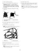
Страница 16: ...nd wait for all moving parts to stop 2 Rotate the discharge chute so that it faces forward 3 Remove the discharge chute the discharge chute handle and the chute seal by removing the 3 large screws and one small screw Figure 33 Figure 33 1 Fuel tank cap 4 Small screw 2 Large screws 3 5 Chute seal 3 Discharge chute 4 Remove the 4 screws that secure the shroud Figure 34 Figure 34 1 Screw 4 3 Spark pl...

Страница 17: ...3 Connect the wire to the spark plug Note Ensure that the breather tube is routed above the spark plug wire as shown in Figure 36 Figure 36 1 Breather tube 2 Carburetor drain bolt 14 Remove the fuel tank cap 15 Install the shroud with the screws you removed in step 4 Note Ensure that the upper and lower shrouds fit together in the side grooves 16 Install the fuel tank cap 17 Install the chute seal...

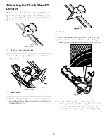
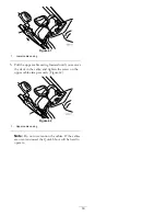
Страница 18: ...ure 38 1 Cable clamps 2 Position the Quick Shoot control between the two arrows located on the right hand side of the upper handle Figure 39 Figure 39 1 Arrows 3 Rotate the discharge chute so that it faces straight ahead and the arrow on the back of the discharge chute aligns with the arrow on the shroud Figure 40 Figure 40 4 Hold the discharge chute in the straight ahead position pull the lower c...

Страница 19: ...ng forward until you remove the slack in the cable and tighten the screw on the upper cable clamp securely Figure 42 Figure 42 1 Upper cable casing Note Do not over tension the cables If the cables are over tensioned the Quick Shoot will be hard to operate 19 ...

Страница 20: ...ngine start it a third time and run the engine until it will not start 6 Drain the fuel in the carburetor through the carburetor drain bolt Figure 36 into an approved gasoline container 7 Dispose of unused fuel properly Recycle it according to local codes or use it in your automobile 8 While the engine is still warm change the engine oil Refer to Changing the Engine Oil 9 Remove the spark plug 10 ...

Страница 21: ...Notes 21 ...
Страница 22: ...The Toro Company and its affiliate Toro Warranty Company jointly warrant to the initial owner and each subsequent purchaser that the engine is free from defects in materials and workmanship which cause the engine to fail to conform with applicable regulations for a period of two years Failures caused by abuse neglect or improper maintenance are not covered The use of add on or modified parts can b...

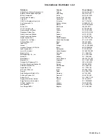
Страница 23: ...08 Ibea S P A Italy 39 0331 853611 Irriamc Portugal 351 21 238 8260 Irrigation Products Int l Pvt Ltd India 86 22 83960789 Jean Heybroek b v Netherlands 31 30 639 4611 Lely U K Limited United Kingdom 44 1480 226 800 Maquiver S A Colombia 57 1 236 4079 Maruyama Mfg Co Inc Japan 81 3 3252 2285 Metra Kft Hungary 36 1 326 3880 Mountfield a s Czech Republic 420 255 704 220 Munditol S A Argentina 54 11 ...

Страница 24: ...e of the product If for any reason it is impossible for you to contact your seller you may contact any Toro Authorized Distributor to arrange service 2 Bring the product and your proof of purchase sales receipt to the Service Dealer If for any reason you are dissatisfied with the Service Dealer s analysis or with the assistance provided contact us at Customer Care Department Consumer Division The ...

Отзывы: