Toro 30822 Скачать руководство пользователя страница 7

7

Check Condition of Deck

Make sure cutting chambers are in good condition.
Straighten any bends in chamber components to assure
correct blade tip/chamber clearance.

After Operating

To ensure optimum performance, clean underside of mower
housing. If residue is allowed to build up in mower
housing, cutting performance will decrease.

Maintenance

Note: Determine the left and right sides of the machine from the normal operating position.

Caution

If you leave the key in the ignition switch, someone could accidently start the engine and
seriously injure you or other bystanders.

Remove the key from the ignition and disconnect the wire from the spark plug before you do any
maintenance. Set the wire aside so that it does not accidentally contact the spark plug.

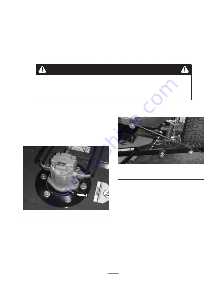
Greasing the Bearings

Each cutting deck has two grease fittings per spindle. Either
fitting can be used, which ever is more accessible. If
machine is operated under normal conditions, lubricate
blade spindle bearings (Fig. 6) with No. 2 general purpose
lithium base grease or molybdenum base grease, after every
50 hours of operation. Pump grease into fitting until a small
amount appears at bottom of spindle housing (under deck).

Figure 6

Cutting Deck Service Latch

When servicing cutting decks, use the service latch to
prevent injury.

1. Center cutting deck sidewinder with the traction unit.

2. Raise cutting decks to transport position.

3. Set parking brake and turn off machine.

4. Release latch rod (Fig. 7) from front carrier frame

retainer.

1

Figure 7

1.

Service latch hook

5. Lift outside of front cutting decks and place latch over

frame pin mounted on front of operators platform
(Fig. 7).

6. Sit on operator seat and start traction unit.

7. Lower cutting decks to mow position.

8. Turn off machine and remove key.

9. Reverse procedure to unlatch cutting decks.

Содержание 30822

Страница 1: ...Operator s Manual English EN Form No 3326 156 27 Rotary Cutting Deck Groundsmaster 3500 Traction Unit Model No 30822 210002001 and Up...

Страница 2: ...and produces safe products you are responsible for operating the product properly and safely Whenever you need service genuine Toro parts or additional information contact an Authorized Service Dealer...

Страница 3: ...43 8480 104 1086 Specifications Note Specifications and design subject to change without notice Optional Equipment Mulching Baffle Kit contains parts for three decks Model No 30824 Dimensions Overall...

Страница 4: ...le tapered roller bearing ductile iron housing which withstands multiple impact tests Discharge Rear even clipping distribution in wet or dry conditions Mulching Baffle Optional Pre drilled mounting h...

Страница 5: ...ber but will cause the cutting deck to reach their maximum up travel sooner Rear Cutting Decks For all heights of cut the rear cutting deck should be mounted in the rear mounting holes Fig 1 Adjusting...

Страница 6: ...n rear opening and secure with 5 flange head screws Fig 5 1 m 5421 Figure 5 1 Mulching baffle 3 Verify that mulching baffle does not interfere with either tip of blade and does not protrude inside the...

Страница 7: ...s two grease fittings per spindle Either fitting can be used which ever is more accessible If machine is operated under normal conditions lubricate blade spindle bearings Fig 6 with No 2 general purpo...

Страница 8: ...on and not damaged 5 Grease spindle Blade Plane The rotary deck comes from the factory preset at 2 00 inch height of cut and blade rake of 0 31 inch The left hand and right hand heights are also prese...

Страница 9: ...height then no adjustment is needed for that side Adjust other side to within 03 in of correct side 7 Adjust right and or left height of cut brackets by repeating steps 1 thru 3 8 Secure carriage bol...

Страница 10: ...raight and parallel lay blade on a level surface and check its ends Ends of blade must be slightly lower than the center and cutting edge must be lower than the heel of the blade This blade will produ...

Страница 11: ...ttempt to re use these seals Bearing Removal Reference The bearings are pressed on to the shaft 0003 0016 in interference and loose fit to housing 0020 0035 in clearance 1 Remove spiral retaining ring...

Страница 12: ...inner and outer race 2 Insert spacer Fig 18 3 Press second bearing into roller housing Fig 18 pressing equally on inner and outer race until the inner race comes in contact with spacer 4 Install roll...

Отзывы: