


Replacing the Hydraulic Filters
Service Interval:
After the first 200 hours
Every 800 hours
Change the 2 hydraulic filters initially after the first 200
operating hours. Thereafter, change the filters after
every 800 operating hours, in normal conditions.
Use Toro replacement filters (Part No. 94-2621 for the
left side of the machine and 75-1310 for the right side
of the machine).
Important:
Use of any other filter may void the
warranty on some components.
1. Position the machine on a level surface, lower the
cutting units, stop the engine, engage the parking
brakes, and remove the ignition key.
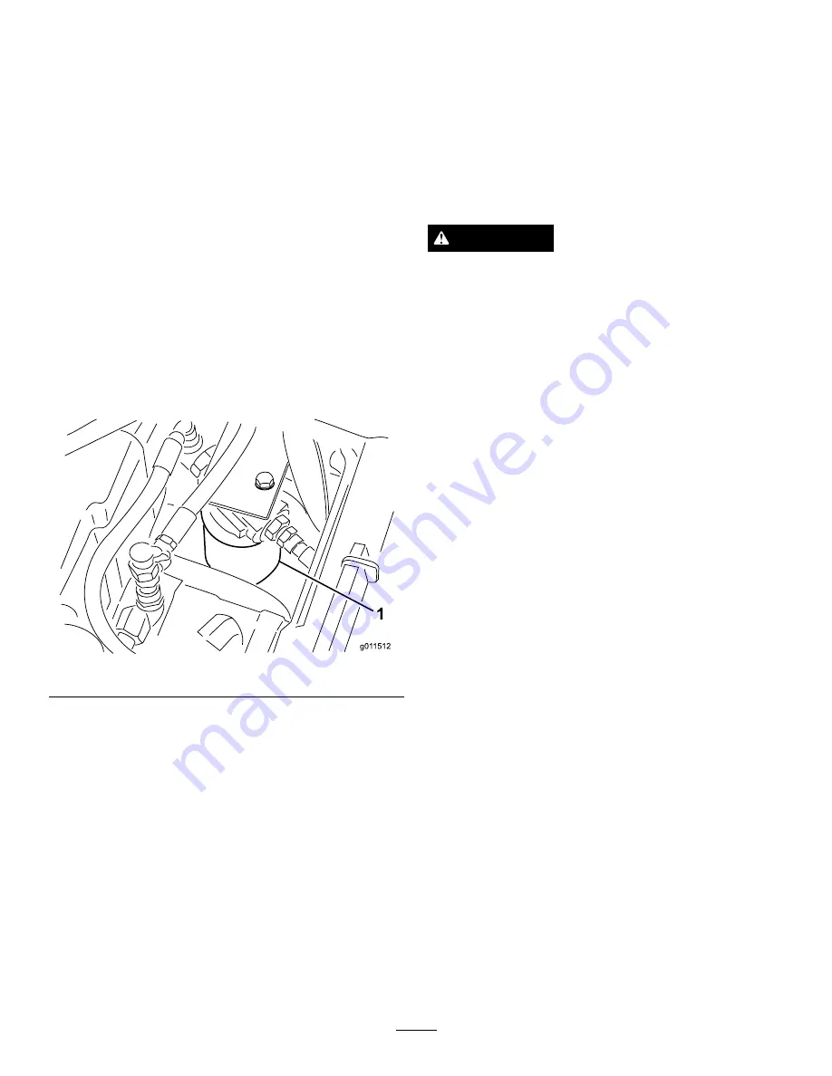
2. Clean the area around the filter mounting area. Place
a drain pan under the filter and remove the filter
(Figure 75).
Figure 75
3. Lubricate the new filter gasket and fill the filter with
hydraulic fluid.
4. Ensure that the filter mounting area is clean. Screw
the filter on until the gasket contacts the mounting
plate; then tighten the filter an additional 1/2 turn.
5. Start the engine and let it run for about two minutes
to purge air from the system. Stop the engine and
check for leaks.
Checking the Hydraulic Lines
and Hoses
Service Interval:
Every 2 years
Inspect the hydraulic lines and hoses daily for
leaks, kinked lines, loose mounting supports, wear,
loose fittings, weather deterioration, and chemical
deterioration. Make all necessary repairs before
operating.
WARNING
Hydraulic fluid escaping under pressure can
penetrate skin and cause injury.
•
Make sure all hydraulic fluid hoses and lines are
in good condition and all hydraulic connections
and fittings are tight before applying pressure to
the hydraulic system.
•
Keep your body and hands away from pin
hole leaks or nozzles that eject high pressure
hydraulic fluid.
•
Use cardboard or paper to find hydraulic leaks.
•
Safely relieve all pressure in the hydraulic system
before performing any work on the hydraulic
system.
•
Seek immediate medical attention if fluid is
injected into skin.
Adjusting the Counterbalance
Pressure
The counterbalance test port (Figure 76) is used
to test the pressure in the counterbalance circuit.
Recommended counterbalance pressure is 470 psi (3241
kPa). To adjust the counterbalance pressure, loosen the
locknut, rotate the adjusting screw (Figure 76) clockwise
to increase the pressure or counterclockwise to decrease
the pressure and tighten the lock nut.
Note:
All three side cutting units castor wheels should
remain on the ground with counterbalance applied.
50
Содержание 30447
Страница 60: ...Schematics g014815 Electrical Schematic Rev D 60...
Страница 61: ...g017775 Electrical Schematic Rev D 61...
Страница 62: ...g017776 Electrical Schematic Rev D 62...
Страница 63: ...g017777 Electrical Schematic EU GM 4000 4100 Rev D 63...
Страница 64: ...g017778 Electrical Schematic EU GM 4010 Rev D 64...
Страница 65: ...g017779 Electrical Schematic US GM 4000 4100 Rev D 65...
Страница 66: ...g017780 Electrical Schematic US GM 4010 Rev D 66...
Страница 67: ...g017781 Electrical Schematic US GM 4110 Rev D 67...
Страница 68: ...g017782 Electrical Schematic GM 4010 Rev D 68...
Страница 69: ...g017783 Electrical Schematic GM 4110 Rev D 69...
Страница 70: ...g017784 Electrical Schematic GM 4110 Cab Rev D 70...
Страница 71: ...g017785 Electrical Schematic GM 4110 Cab Rev D 71...
Страница 72: ...Hydraulic Schematic Rev B 72...
Страница 73: ...Notes 73...
Страница 74: ...Notes 74...
Страница 75: ...Notes 75...


