background image

18

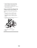
Using the Parking Brake

Stop on level ground, disengage drives, engage parking
brake, shut off engine and remove key. Always set the
parking brake when you stop the machine or leave it
unattended.

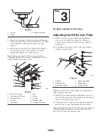
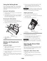
Setting the Parking Brake

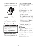
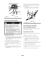
1. Pull the upper control bar (Fig. 14) rearward and hold

it in this position.

2. Lift the parking brake lock (Fig. 14) up and gradually

release the upper control bar. The brake lock should
stay in the set (locked) position.

Releasing the Parking Brake

1. Pull rearward on the upper control bar (Fig. 14).

Lower the parking brake lock to the released position.

2. Gradually release the upper control bar.

1

2

m–5233

3

Figure 14

1.

Upper control bar

2.

Parking brake lever (set
position)

3.

Fixed bar

Starting and Stopping the
Engine

Starting the Engine

1. Make sure spark plug wire(s) are


installed on spark

plug(s) and fuel valve is open.

2. Move the shift lever to neutral, set the parking brake

and turn ignition key to run.

3. Move the throttle control to the choke position before

starting a cold engine.

Note: A warm or hot engine usually does not require any
choking. To start a warm engine, move throttle control to
the fast position.

4. Grasp recoil starter handle firmly and pull out until

positive engagement results; then pull handle
vigorously to start engine and allow rope to recoil
slowly.

Important


Do not pull recoil rope to its limit or let go

of the starter handle when rope is pulled out because rope
may break or recoil assembly may be damaged.
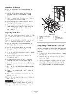
Stopping the Engine

1. Move the throttle lever to slow (Fig. 15).

2. Let engine idle for 30 to 60 seconds before turning the

ignition key to off.

3. Turn the ignition key to off (Fig. 15).

1

2

m–6443

Figure 15

1.

Throttle lever

2.

Ignition key

4. Set the parking brake and remove key.

5. Pull wire off spark plug(s) to prevent possibility of

accidental starting before storing machine.

6. Close fuel shut off valve before storing machine.

Important


Make sure fuel shut off valve is closed

before transporting or storing machine, as fuel leakage
may occur.

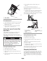
Operating the Mower Blade
Control (PTO)

The blade control switch (PTO) in conjunction with the
blade control bail engages and disengages power to the
electric clutch and mower blades.

Engaging the Mower Blades (PTO)

1. Release the upper control bar to stop the machine

(Fig. 16).

2. To engage blade, squeeze blade control bail against

upper control bar (Fig. 16).

Содержание 30321

Страница 1: ...Operator s Manual Domestic English EN Form No 3327 382 Mid Size Mower ProLine T Bar Gear 17 HP with 44 in Side Discharge Mower Model No 30321 Serial No 230000001 and Up...

Страница 2: ...e Handle Assembly 13 Installing the Shift Lever Plate and Fuel Tank 13 Adjusting the Shift Lever Plate 14 Installing the Control Rods 15 Page Installing the Hairpin Cotter Pins and Washers 16 Operatio...

Страница 3: ...cturers that do not meet American National Standards Institute certification will cause noncompliance of this machine Improper use or maintenance by the operator or owner can result in injury To reduc...

Страница 4: ...eet away from the cutting unit Look behind and down before backing up to be sure of a clear path Keep pets and bystanders away Slow down and use caution when making turns and crossing roads and sidewa...

Страница 5: ...l slopes and ramps require extra caution If you feel uneasy on a slope do not mow it DO Remove obstacles such as rocks tree limbs etc from the mowing area Watch for holes ruts or bumps Tall grass can...

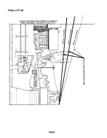
Страница 6: ...6 Slope Chart...

Страница 7: ...7...

Страница 8: ...Safety decals and instructions are easily visible to the operator and are located near any area of potential danger Replace any decal that is damaged or lost 43 8480 52 2010 66 1340 67 5360 68 8340 8...

Страница 9: ...9 98 0776 98 4387 1 Warning wearhearing protection 104 8186 104 8569 106 5532 106 0699 105 0884 106 0635...

Страница 10: ...10 106 5494 106 5499 1 Engine stop 2 Engine start 3 Move the control bar to the handle then pull the knob 106 5505...

Страница 11: ...possible then refuel such equipment on a truck or trailer from a portable container rather than from a gasoline dispenser nozzle If a gasoline dispenser nozzle must be used keep the nozzle in contact...

Страница 12: ...e Bolt 5 16 x 7 8 inch Lock washer 5 16 inch Washer 5 16 inch Spring Hose clamp 1 1 2 2 4 2 1 Installing shift lever plate and fuel tank 3 No parts needed Adjusting the shift lever plate 4 Clevis pin...

Страница 13: ...e Handle assembly must be installed before fuel tank is installed 2 Step Parts needed for this step 1 Fuel tank with studs installed 1 Shift lever plate 2 Bolts 5 16 x 7 8 inch 2 Lock washers 5 16 inc...

Страница 14: ...for this step Adjusting the Shift Lever Plate 1 Shift lever to second gear and check alignment of lever in slot of shifter lever plate The clearance between top and bottom of the shift lever should b...

Страница 15: ...fitting 2 3 1 2inch 89 mm 3 Idler bracket 4 Clevis pin washer and hairpin cotter 5 Rod fitting 6 Hole F 3 Check the gap between upper control bar and fixed bar with wheel drive fully engaged Gap shou...

Страница 16: ...ake lever 3 Fixed bar 5 Step Parts needed for this step 2 Hairpin cotter pins Installing the Hairpin Cotter Pins and Washers Unused height of cut spacers may be stored on posts and retained by a hairp...

Страница 17: ...on with control bail to release clutch brake and engage clutch to drive mower blades Gear Shift Lever Transmission has five forward speeds neutral and reverse and has an in line shift pattern Importan...

Страница 18: ...start a warm engine move throttle control to the fast position 4 Grasp recoil starter handle firmly and pull out until positive engagement results then pull handle vigorously to start engine and allow...

Страница 19: ...h time Note If the safety system does not operate as described below have an Authorized Service Dealer repair the safety system immediately 1 Set the parking brake and start the engine refer to Starti...

Страница 20: ...ine until drive wheels contact curb Fig 18 6 Lower the front of the machine Fig 18 Note Both drive wheels should contact the curb and caster wheels straight 7 At the same time engage lower control bar...

Страница 21: ...he mower because the grass deflector routes material down toward the turf If the grass deflector is ever damaged replace it immediately Never put your hands or feet under the mower Never try to clear...

Страница 22: ...The handle position can be adjusted to match the operator s height preference 1 Remove hairpin cotter washer and clevis pin securing control rod fitting to idler bracket Fig 22 1 3 2 4 4 5 6 m 5316 Fi...

Страница 23: ...Mid Size Weight Kit A weight kit is available for this machine This kit is optional and can be obtain from an Authorized Service Dealer The weight kit mounted in the front position is required when a...

Страница 24: ...eck Electric Clutch adjust Engine clean outside 200 Hours Fuel Filter replace Oil Filter change 200 hours or every other oil change Paper Air Cleaner replace 250 Hours Transmission Couplings grease1 4...

Страница 25: ...the foam element in liquid soap and warm water When the element is clean rinse it thoroughly 2 Dry the element by squeezing it in a clean cloth 3 Put one or two ounces of oil on the element Fig 26 Sq...

Страница 26: ...ck fully onto the filler tube Fig 28 Pull the dipstick out and look at the metal end If oil level is low slowly pour only enough oil into the filler tube to raise the level to the full mark Important...

Страница 27: ...kcase with the proper type of new oil refer to Engine Oil Service page 26 Servicing the Spark Plug Service Interval and Specification Check the spark plug s after every 100 operating hours Make sure t...

Страница 28: ...and wait for all moving parts to stop before leaving the operating position 3 Clean the grease fittings with a rag Make sure to scrape any paint off the front of the fitting s 4 Connect a grease gun...

Страница 29: ...e Interval Specification Maintain the air pressure in the front and rear tires as specified Check the pressure at the valve stem after every 40 operating hours or monthly whichever occurs first Fig 36...

Страница 30: ...age 18 5 To adjust the brake remove the hair pin cotter and washer from the brake lever and trunnion Fig 38 6 Rotate the wing nut clockwise to increase the braking pressure 7 Rotate the wing nut count...

Страница 31: ...fuel line off the valve Fig 40 Open fuel shut off valve and allow gasoline to drain into a gas can or drain pan Note Now is the best time to install a new fuel filter because the fuel tank is empty R...

Страница 32: ...k plug s Inspecting the Blades 1 Inspect the cutting edges Fig 42 If the edges are not sharp or have nicks remove and sharpen the blades Refer to Sharpening the Blades on page 33 2 Inspect the blades...

Страница 33: ...nt of material is removed from both cutting edges 1 m 1854 Figure 46 1 Sharpen at original angle 2 Check the balance of the blade by putting it on a blade balancer Fig 47 If the blade stays in a horiz...

Страница 34: ...A 1 5 16 inch 33 mm 1 4 inch 6 mm 5 Straight edge 6 Carrier frame cross tube Checking Engine Deck Height 1 Disengage the PTO and set the parking brake 2 Stop the engine remove the key and wait for al...

Страница 35: ...cations A and B 5 Caster spacers Checking the Deck Front to Rear Pitch 1 Check the tire pressure on both deck and traction unit 2 Position one blade front to rear Fig 52 Measure at C and D locations F...

Страница 36: ...h 6 mm A Front B m 1078 Figure 55 MEASURE FROM CUTTING EDGE TO A LEVEL SURFACE m 2550 Figure 56 Changing the Side to Side Leveling Changing the side to side leveling is done by adjusting tire pressure...

Страница 37: ...e Fig 59 6 Tighten the bottom two mounting screws enough to allow the belt to pass between the drive pulley and idler support Fig 59 2 m 1722 1 4 3 5 Figure 59 1 Top capscrew 2 Idler bracket 3 Idler s...

Страница 38: ...ting unit then reinstall and tighten the knobs 11 Install the carrier frame cover and rubber washers onto the cutting unit then install and tighten the hand knobs 4 3 1 5 3 2 6 m 6529 Figure 61 1 Deck...

Страница 39: ...rect installation and to maintain a level deck 4 2 1 3 2 m 6372 Figure 63 1 Locking Pin 2 Spacers locate as required 3 Carrier frame mounting tube 4 Caster wheel fork 4 Insert a pin punch into the mou...

Страница 40: ...the wheel bolt and locknut Tighten the locknut until the spanner bushing bottoms against the inside of the caster forks Fig 65 7 Grease the fitting on the caster wheel Replacing the Grass Deflector A...

Страница 41: ...D1 D4 C2 D6 HOUR METER OPTIONAL PK W AC AC IGNITION MODULE REG MAG SPARK PLUG PK 7 5A F1 S2 CLUTCH SW MOMENTARY PK G KEY SW S3 BAIL SW NORMALLY OPEN BN OR PK KEY SWITCH NONE G M OFF ON M S1 IGNITION W...

Страница 42: ...to distribute conditioned fuel through the fuel system 5 minutes B Stop engine allow to cool and drain the fuel tank refer to Fuel Tank page 31 or operate engine until it stops C Restart engine and r...

Страница 43: ...2 Clean air cleaner element 3 Oil level in crankcase is low 3 Add oil to crankcase 4 Cooling fins and air passages under engine blower housing are plugged 4 Remove obstruction from cooling fins and ai...

Страница 44: ...blade s is are bent 2 Install new cutting blade s 3 Mower is not level 3 Level mower from side to side and front to rear 4 Underside of mower is dirty 4 Clean the underside of the mower 5 Tire pressur...

Страница 45: ......

Страница 46: ......

Страница 47: ......

Страница 48: ...ered There is no other express warranty except for special emission system coverage on some products This express warranty does not cover the following Cost of regular maintenance service or parts suc...

Отзывы: