


23
m–3779
1
4
3
2
4
6
5
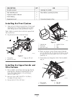
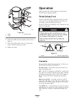
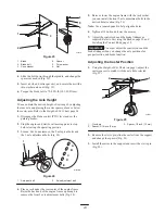
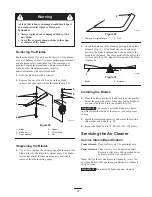
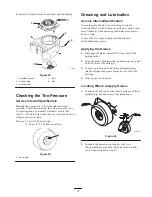
Figure 23
1.
Blade
2.
Blade bolt
3.
Cone washer
4.
Spacer
5.
Thin washer
6.
Nut
4. Slide the bolt down through the spindle, and change the
spacers as needed (Fig. 23).
5. Insert a bolt, add extra spacer(s), and secure them with a
thin washer and a nut (Fig. 23).
6. Torque the blade bolt to 75–80 ft-lb (101–108 N
m).
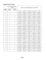
Adjusting the Axle Height
You can obtain the desired height-of-cut range by adjusting
the rear axle and placing the caster spacers above or below
the caster arm. Refer to the Height-of-Cut Chart, page 24.
1. Disengage the blade control (PTO) lever and set the
parking brakes.
2. Stop the engine and wait for all moving parts to stop
before leaving the operating position.
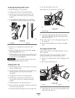
3. Loosen, but do not remove, the 2 axle pivot bolts and
the 2 axle adjustment bolts (Fig. 24).
m–3789
1
2
A
B
C
D
E
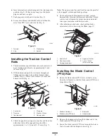
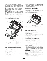
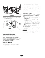
Figure 24
1.
Axle pivot bolt
2.
Axle adjustment bolt
4. Place a jack under the rear center of the engine frame.
Raise the back end of the engine frame up enough to
remove the front 2 axle adjustment bolts (Fig. 24).
5. Raise or lower the engine frame with the jack so that
you can install the front 2 axle adjustment bolts in the
desired hole location (Fig. 24).
Note: Use a tapered punch to help align the holes.
6. Tighten all 4 bolts and lower the mower.
7. Adjust the control rods and the brake linkages as
required. Refer to Servicing the Brakes, page 32 and
Installing the Control Rods, page 15.
Important
You must adjust the control rods and the
brake linkage when you change the axle positions for
proper traction and brake function.
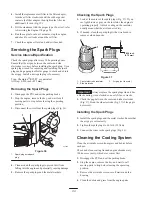
Adjusting the Caster Position
1. Using the Height-of-Cut Chart (on page ), adjust the
caster spacers to match with the axle hole selected
(Fig. 25).
m–3791
1
3
2
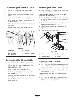
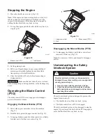
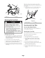
Figure 25
1.
Clevis pin
2.
Spacer, 3/16 inch (5 mm)
3.
Spacer, 1/2 inch (13 mm)
2. Remove the clevis pin, slide the caster from the support,
and change the spacers (Fig. 25).
3. Install the caster in the support and insert the clevis pin
(Fig. 25).


