Toro 200000001 Скачать руководство пользователя страница 7

7

Gauging Plow Depth

Normally, you will be plowing at the maximum depth set

by the blade; however, the plow is also equipped with a

gauge to allow you to lift the plow and determine how

high above maximum depth you are plowing.

The gauge is located on the the left side of the plow facing

the traction unit.  A rod assembly runs from the gauge to

the ground.  When the plow is lifted, the indicator on the

gauge moves down.  Marks on the gauge show the number

of inches lower or higher than the maximum depth that

you are plowing.  The gauge reads from +2 to –3 inches

(+5 to –7.6 cm), with zero being the maximum depth on

bare ground and –3 being 3 inches (7.6 cm) above

maximum depth.  Figures 5 and 6 illustrate the gauge.

m–4145

1

2

Figure 5

1. Depth gauge

2. Gauge locking lever

m–4336

1

2

Figure 6

1. Gauge rod assembly

2. Parallel to the ground

When plowing bare ground, maximum depth is indicated

on the gauge as the zero mark.  You can plow down to the

+1 mark, but in this case you will be contacting the

ground with the coulter axle.  Plowing any lower may

damage the coulter.

When plowing grass covered ground, the gauge will read

about an inch lower than the actual depth because of the

grass.  In this case, lower the plow to the desired coulter

depth and note the reading on the gauge.

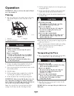
If you are transporting the plow or are plowing rough

terrain, you can lock the gauge at the +2 position to keep

it from being damaged.  To lock the gauge, manually raise

it to the +2 position and move the locking lever to the left.

Tips for Plowing

When plowing long runs it is advisable to install two

hairpin cotters through the spring and quick attach pins

on the mount plate (Fig. 7).  This will ensure that the

vibration of the plow will not cause the pins to come

loose.

Note:

 If your quick attach pins do not have holes in them

for the hairpin cotters, contact your dealer to obtain new

quick attach pins.

m–4056

1

Figure 7

1. Hairpin cotters

To reduce wear on the traction unit drive chain (if your

model has one), tighten the chain so there is only 2 in.

(5 cm) of slack on the upper span (refer to your

traction unit 

Operator’s Manua

l for instructions).

Clean the area of trash, branches and rocks before

plowing to prevent equipment damage.

Always begin plowing with the slowest ground speed

possible.  Increase speed if conditions permit, but do

not allow the tires or tracks to spin.  Spinning the

tracks or tires will cause turf damage and place stress

on the traction unit.

Always use full throttle (maximum engine speed)

when plowing.

Always plow backwards (i.e., in reverse).

If your traction unit has a speed selector and a flow

divider, move the speed selector to slow (turtle) and

the flow divider to the 10 o’clock position.

Avoid sharp turns when plowing to increase

productivity and minimize ground disturbance.

Содержание 200000001

Страница 1: ...Operator s Manual Original Instructions EN Register your product at www Toro com Form No 3353 857 Rev A Vibratory Plow for Compact Utility Loaders Model No 22910 200000001 Up ...

Страница 2: ...d be extremely careful DANGER signals an extreme hazard that will cause serious injury or death if the recommended precautions are not followed WARNING signals a hazard that may cause serious injury or death if the recommended precautions are not followed CAUTION signals a hazard that may cause minor or moderate injury if the recommended precautions are not followed Two other words are also used t...

Страница 3: ...Over time your hearing may be impaired if unprotected HOW TO AVOID THE HAZARD Wear hearing protection during operation WARNING POTENTIAL HAZARD When the plow is out of the ground bystanders could be injured by the swinging plow The traction unit could be overturned by the inertia of the swinging plow WHAT CAN HAPPEN You or bystanders could be crushed by the traction unit or plow HOW TO AVOID THE H...

Страница 4: ... stability rating for the hill orientation you want to travel in the table below then find the degree of slope for the same rating and orientation in the Stability Data section of the traction unit operator s manual Orientation Stability Rating Front Uphill C Rear Uphill D Side Uphill C IMPORTANT If your traction unit has a rear operator s platform the counterweight must be used on the platform wh...

Страница 5: ...n 3 Blade Removing the Plow from the Traction Unit Refer to your traction unit operator s manual for complete instructions on removing attachments from the traction unit and disconnecting hydraulic hoses 1 With the plow raised above the ground stop the engine 2 Remove the lower click pin and clevis pin securing the blade to the plow to completely remove the blade remove both the upper and lower cl...

Страница 6: ...er to the operator grip to engage the plow 8 Slowly lower the plow into the ground to the desired depth while moving the traction unit backward 9 When finished release the auxiliary hydraulics lever to stop the plow CAUTION POTENTIAL HAZARD When plowing on a hill the plow can swing down hill when raised out of the soil WHAT CAN HAPPEN Due to the weight of the plow if it swings too fast the force c...

Страница 7: ...nsporting the plow or are plowing rough terrain you can lock the gauge at the 2 position to keep it from being damaged To lock the gauge manually raise it to the 2 position and move the locking lever to the left Tips for Plowing When plowing long runs it is advisable to install two hairpin cotters through the spring and quick attach pins on the mount plate Fig 7 This will ensure that the vibration...

Страница 8: ...rease pivot pin fittings X X Gear lube oil check level X Gear lube oil change X Chipped surfaces paint X CAUTION POTENTIAL HAZARD If you leave the key in the ignition switch someone could start the engine WHAT CAN HAPPEN Accidental starting of the engine could seriously injure you or other bystanders HOW TO AVOID THE HAZARD Remove the key from the ignition switch before you do any maintenance Grea...

Страница 9: ...e 4 If the gear lube level is low remove the fill plug Fig 12 and fill the case with gear lube until it is level with the red dot in the gauge m 4147 3 1 2 Figure 12 1 Glass gauge 2 Drain plug 3 Fill plug 5 Replace the fill plug Changing Gear Lube 1 Position the traction unit and plow on a level surface and lower the attachment lift so that the plow is on the ground 2 Stop the engine and remove th...

Страница 10: ...tachment in a clean dry garage or storage area Cover it to protect it and keep it clean Troubleshooting PROBLEM POSSIBLE CAUSES CORRECTIVE ACTION The plow does not operate 1 Hydraulic coupler not completely connected 1 Check and tighten all couplers 2 Damaged hydraulic coupler 2 Check couplers and replace any that are damaged 3 An obstruction in a hydraulic hose 4 Auxiliary valve on the traction u...

Страница 11: ...11 ...

Страница 12: ......

Отзывы: