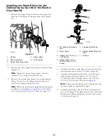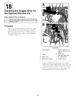
Figure 67
1.
Agitation supply hose—2.5 x 72 cm (1 x 28-1/4 inches)
3.
Assemble the quick-connect fitting (straight barbed)
of the agitation supply hose onto the quick coupling
of the agitation throttle valve with the retainer that is
supplied with the hose (
Installing the Bypass Hose—Machines
without the Optional Spray Wand Kit or
Electric Hose Reel Kit
If your machine has the optional spray wand kit or electric
hose reel kit, skip this procedure. You will install the bypass
hose in
17 Installing the Shutoff Valve and Hoses for the
Optional Spray Gun Kit or Electric Hose-Reel Kit (page 40)
.
1.
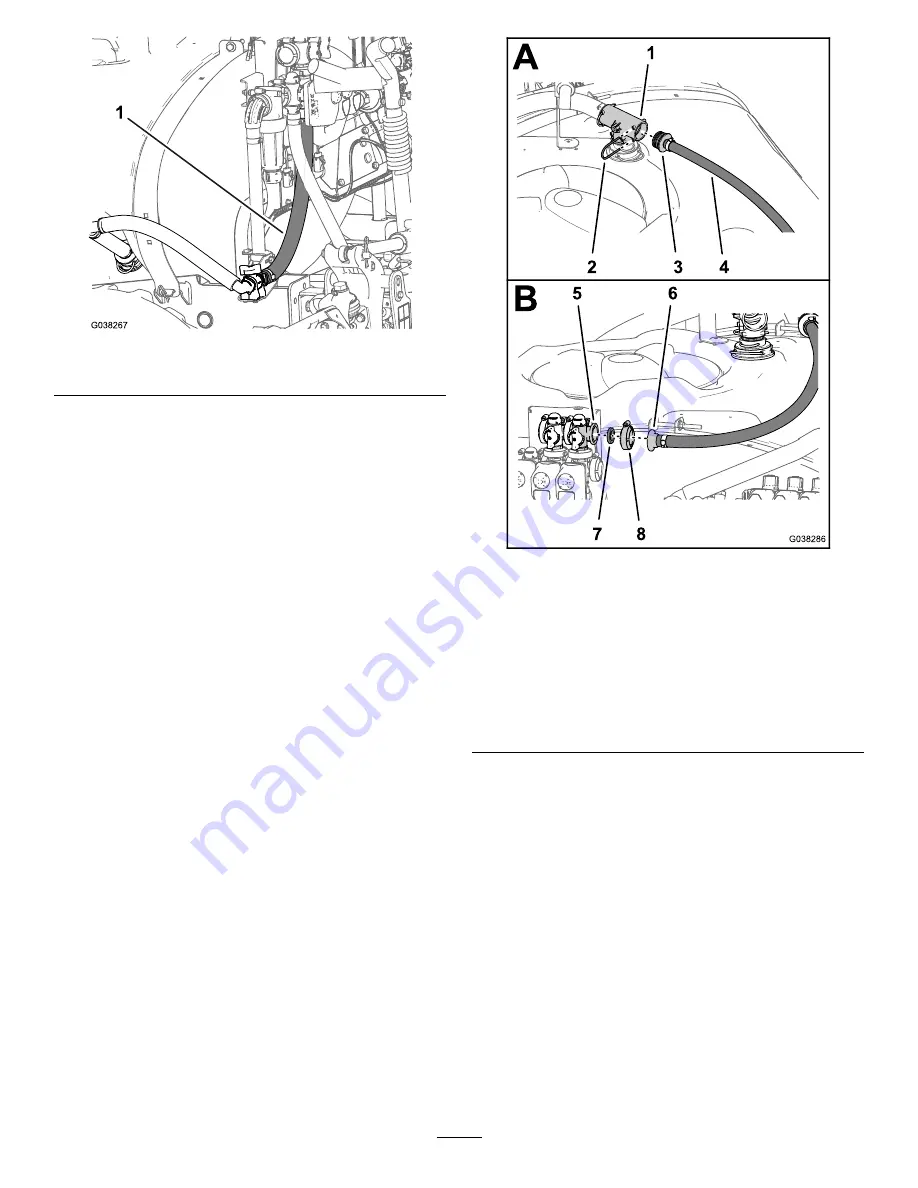
Assemble the straight barbed fitting of the bypass
hose—2.5 x 110 cm (1 x 43-1/2 inches) into the rear
port of the T-fitting at the top of the sprayer tank
(
).
Figure 68
1.
T-fitting
5.
Flange—bypass valve
(master-spray valve
position)
2.
Retainer
6.
Straight barbed fitting
3.
Straight barbed fitting
7.
Gasket—25 x 35 mm (1 x
1-3/8 inches)
4.
Bypass hose—2.5 x 110
cm (1 x 43-1/2 inches)
8.
Flange clamp—40 to
64 mm (1-9/16 to 2-1/2
inches)
2.
Secure the straight barbed fitting to the T-fitting
with the retainer that you removed in step
of
Disconnecting the Return, Sprayer-Supply, and Bypass
Hoses (page 14)
.
3.
Route the bypass hose to the bypass valve located
above the master-spray valve as shown in
33
Содержание 136-0372
Страница 61: ...Schematics Flow Diagram Rev A 61...
Страница 62: ...Notes...
Страница 63: ...Notes...
Страница 64: ......

