background image

Form No. 3389-137 Rev A

Multi Pro

®

WM Turf Sprayer Finishing Kit

Manual Workman

®

Utility Vehicle

Model No. 131-3302

Installation Instructions

WARNING

CALIFORNIA

Proposition 65 Warning

This product contains a chemical or chemicals known to the State of California to

cause cancer, birth defects, or reproductive harm.

Use of this product may cause exposure to chemicals known to the State of California

to cause cancer, birth defects, or other reproductive harm.

Installation

Loose Parts

Use the chart below to verify that all parts have been shipped.

Procedure

Description

Qty.

Use

1

Drive-shaft-shield bracket

1

Install the drive-shaft shield on the
sprayer pump.

PTO drive shaft

1

Woodruff key

1

Set screw

2

Drive-shaft shield

1

Clip

2

2

Flange-head bolt (1/4 x 3/4 inch)

2

Install the PTO shaft and the drive-shaft
shield to the sprayer pump.

Hydraulic hose (5/8 x 55.6 inches)

1

Hydraulic hose (5/8 x 85.2 inches)

1

Male quick coupler

1

Female quick coupler

1

Tube clamp

2

Clamp bolt (5/16 x 1-1/2 inches)

1

3

Cable tie

3

Install the hydraulic hoses for the boom
lift cylinders.

4

No parts required

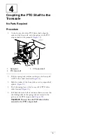
Couple the PTO shaft to the transaxle.

Note:

Remove the cargo box or flatbed from the vehicle before installing this kit; refer to the

Operator’s Manual

for the vehicle.

Note:

For Non-TC models, install the Rear PTO Kit before installing this kit; contact your Authorized Toro Distributor

about purchasing this kit.

© 2014—The Toro® Company
8111 Lyndale Avenue South
Bloomington, MN 55420

Register at www.Toro.com.

Original Instructions (EN)

Printed in the USA

All Rights Reserved

*3389-137* A


Содержание 131-3302

Страница 1: ...f key 1 Set screw 2 Drive shaft shield 1 Clip 2 2 Flange head bolt 1 4 x 3 4 inch 2 Install the PTO shaft and the drive shaft shield to the sprayer pump Hydraulic hose 5 8 x 55 6 inches 1 Hydraulic hose 5 8 x 85 2 inches 1 Male quick coupler 1 Female quick coupler 1 Tube clamp 2 Clamp bolt 5 16 x 1 1 2 inches 1 3 Cable tie 3 Install the hydraulic hoses for the boom lift cylinders 4 No parts requir...

Страница 2: ...ve shaft shield bracket onto the sprayer pump with the 2 bolts removed in step 1 as shown in Figure 2 Figure 2 1 Drive shaft shield bracket 2 Bolts from the sprayer pump 4 Torque the bolts to 23 to 26 N m 17 to 21 ft lb 2 Install the PTO Shaft and the Drive Shaft Shield to the Sprayer Pump Parts needed for this procedure 1 PTO drive shaft 1 Woodruff key 2 Set screw 1 Drive shaft shield 2 Clip 2 Fl...

Страница 3: ...o the shield support bracket with 2 flange head bolts 1 4 x 3 4 inch and 2 clips Figure 5 Figure 5 1 Flange head bolt 2 3 Drive shaft shield 2 Clip 2 3 Installing the Hydraulic Hoses for the Boom Lift Cylinders Parts needed for this procedure 1 Hydraulic hose 5 8 x 55 6 inches 1 Hydraulic hose 5 8 x 85 2 inches 1 Male quick coupler 1 Female quick coupler 2 Tube clamp 1 Clamp bolt 5 16 x 1 1 2 inch...

Страница 4: ...om the T fitting in the hydraulic tube next to the transmission oil filter Figure 8 Figure 8 1 T fitting 2 Transmission oil filter 5 Connect the free end of the hose 3 8 x 55 6 inches to the T fitting Figure 8 and torque the swivel nut of the hose to 37 to 45 N m 27 to 33 ft lb 6 Remove the cap from the T fitting in the hydraulic tube next to the hydraulic fluid tank Figure 9 Figure 9 The crosstub...

Страница 5: ...ull the spring lock rubber cowling at the front yolk of PTO drive shaft rearward Figure 10 3 Slide the socket of the front yolk over the output shaft splines Figure 10 4 Push the spring lock of the front yolk of PTO drive shaft forward Figure 10 5 Pull back the front half of the drive shaft to ensure that the locking balls of the spring lock are seated in the groove of the PTO output shaft Figure ...

Страница 6: ...Notes 6 ...

Страница 7: ...Notes 7 ...

Страница 8: ......

Отзывы: