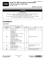


6
Installing the Rocker Switch
Parts needed for this procedure:
1
Rocker switch
1
Kit wire-harness adapter
Procedure
Note:
Ensure that the control console and the electrical
harness are installed; refer to the
Installation Instructions
for
the sprayer.
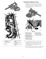
1.
Connect the 3-pin connector of the wire-harness
adapter to the 3-socket connector labeled
CLOSED
LOOP CONTROL KIT
for the console-wire harness
).
Figure 16
1.
Wire-harness adapter
2.
3-socket connector
(labeled
CLOSED
LOOP CONTROL
KIT
—console-wire
harness)
2.
Connect the rocker switch into the 8-socket connector
of the wire-harness adapter.
3.
Install the rocker switch into the opening in the control
console (
) until the switch snaps into place.
Figure 17
1.
Rocker switch
2.
Control console
9


