


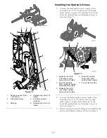


Figure 12
1.
Flange-head bolt (5/16 x
1-1/2 inches)
4.
Hydraulic hose (3/8 x 79
inches)
2.
Tube-clamp halves
5.
Left frame channel
(machine)
3.
Cable tie
6.
Hydraulic hose (3/8 x 61
inches)
Installing the Hydraulic Hoses
1.
Connect the male quick-connect coupler of the
hydraulic hose (3/8 x 79 inches) into the female
quick-connect coupler of the pressure hose for the
boom-lift manifold that you identified in step
as
shown in
Figure 13
1.
Hydraulic hose (3/8
x 79 inches—male
quick-connect coupler)
4.
Boom-lift manifold
hose—tank (male
quick-connect coupler
2.
Boom-lift manifold
hose—pressure (female
quick-connect coupler)
5.
Front of the machine
3.
Hydraulic hose (3/8
x 61 inches—female
quick-connect coupler)
2.
Connect the female quick-connect coupler of the
hydraulic hose (3/8 x 61 inches) onto the male
quick-connect coupler of the tank hose for the
boom-lift manifold that you identified in step
as
shown in
3.
Remove the cap from the T-fitting in the hydraulic tube
next to the hydraulic-oil filter as shown in
7


