


G010581
1
2
3 4
5
6
4
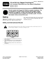
Figure 6
Left side shown
1.
Bagger frame
4.
Hair pin
2.
Clevis end
5.
Bracket on frame
3.
Clevis pin
6.
Washer
7. Insert the bent end of the rod into the bagger frame
as shown in Figure 6. Secure the end of the rod with
a washer and hair pin.
8. Adjust the support rods so that bagger frame is held
secure to the machine frame and seats in the notch
of the angle spacer plate installed previously. Repeat
these steps for each support rod:
A. Loosen the jam nut at the base of the clevis end
of the rod.
B. Rotate the clevis to adjust the rod to the desired
length.
C. Align the holes in the clevis end with the hole in
the bagger frame at the attachment point.
D. Secure the clevis end to the bagger frame using a
clevis pin and hair pin cotter.(Figure 6).
E. Tighten the jam nut.
9. With both rods installed and attached, check the
bagger frame for play. The bagger frame should be
held tight to the machine frame. If necessary, repeat
the previous step to secure the bagger frame.
10.
For remaining steps, consult Bagger Kit 79326
Owner’s Manual
, beginning at Installation step
2.
3
Installing the Chute
Parts needed for this procedure:
1
Straight baffle (48 inch decks only)
1
Curved baffle (54 in decks only)
1
Lock nut (5/16 inch)
1
Hand knob
1
Washer
1
Chute
Procedure
Use this procedure when installing the Finishing Kit on
machines with both 48 and 54 inch decks.
WARNING
An uncovered discharge opening could allow the
lawn mower to throw objects in the operator or
bystander’s direction and result in serious injury.
Also, contact with the blade could occur.
Never operate the lawn mower unless you install
a cover plate, a mulch plate, or a grass chute and
catcher.
Never operate the mower with the discharge opening
uncovered. A discharge cover, mulch cover or bagging
chute must always be used when the mower deck is
operated.
1. Remove fasteners securing the deflector assembly
and existing cut off baffle to the deck (Figure 7).
Retain all fasteners. Remove the fasteners plugging
the forward hole.
4