


Removing the Brake Cable (continued)
g336873
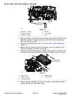
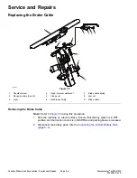
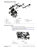
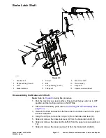
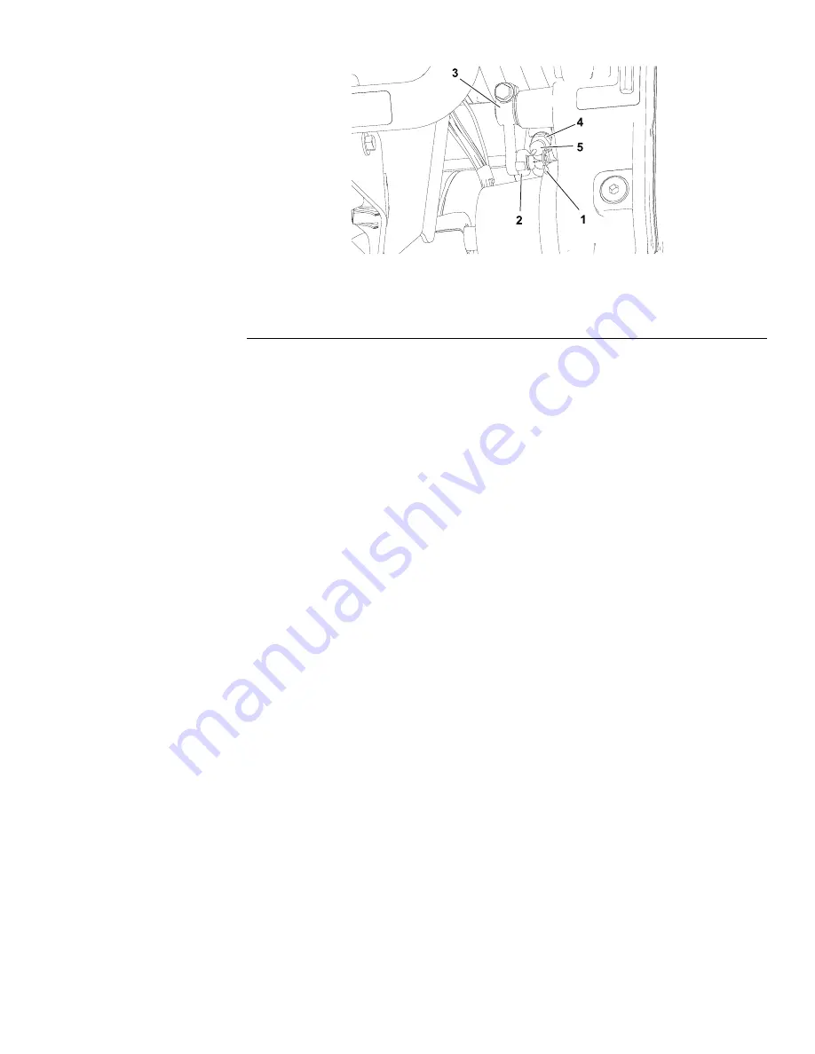
Figure 79
1.
Retaining ring
3.
Brake lever
5.
Brake cable
2.
Cable eyelet
4.
Jam nut
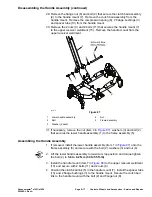
3. Remove the brake cable (item 5 in
) from the brake lever shaft on
the transmission gear box assembly as follows:
A. Loosen the front cable jam nut (4) that secures the brake cable to the
casting slot on the transmission gear box assembly. Remove the brake
cable from the slot.
B. Remove the retaining ring (1) that secures the cable eyelet (2) to the
brake lever (3) on the transmission gear box assembly.
C. Remove the brake cable eyelet (2) from the brake lever (3).
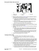
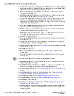
4. Remove the control cover and lower cover from the handle assembly to allow
access to upper end of the brake cable.
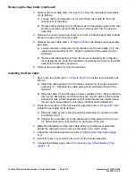
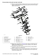
5. Remove the brake cable (item 9 in
) from the brake lever assembly
as follows:
A. Loosen the lower brake cable jam nut (8) that secures the brake cable
(9) to the upper receiver weldment (4). Slide the brake cable from the
upper receiver weldment.
B. Remove the brake cable spring (7) from the spring anchor on the brake
lever assembly (3). Note the orientation of the brake cable spring hook
on the brake lever assembly for assembly purpose.
6. Remove the brake cable (9) from the machine.
Installing the Brake Cable
1. Secure the brake cable (9) to the brake lever assembly as follows:
A. Install the cable spring (7) to the spring anchor on the brake lever
assembly (3).
B. Slide the brake cable into the shift mount bracket slot. Ensure that the jam
nut (8), flat washer and lock washer are both sides of the bracket. Adjust
the jam nuts so that equal amount of cable threads are visible above and
below jam nuts. Leave jam nuts snug until final cable adjustment.
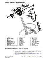
2. Route the brake cable (9) to the transmission gear box assembly and install
the brake cable to the transmission gear box assembly as follows:
A. Install the brake cable eyelet (2) onto the brake lever (3) on transmission
gear box assembly and secure with a snap ring (1).
B. Position the brake cable (5) to the casting slot of the transmission gear
box assembly with a jam nut (4), flat washer and lock washer on each
Greensmaster
®
e1021/e1026
Page 6–5
Controls, Wheels and Accessories : Service and Repairs
20246SL Rev A
Содержание 04831
Страница 4: ...NOTES NOTES Page 4 Greensmaster e1021 e1026 20246SL Rev A ...
Страница 6: ...g340650 Figure 1 Model 04831 shown Preface Page 6 Greensmaster e1021 e1026 20246SL Rev A ...
Страница 14: ...Safety Safety and Instructional Decals Page 1 6 Greensmaster e1021 e1026 20246SL Rev A ...
Страница 46: ...Troubleshooting Battery Charger Error and Fault Codes Page 3 14 Greensmaster e1021 e1026 20246SL Rev A ...
Страница 136: ...Electrical System Service and Repairs Page 5 56 Greensmaster e1021 e1026 20246SL Rev A ...
Страница 162: ...Controls Wheels and Accessories Service and Repairs Page 6 26 Greensmaster e1021 e1026 20246SL Rev A ...
Страница 210: ...Universal Groomer Optional Service and Repairs Page 8 20 Greensmaster e1021 e1026 20246SL Rev A ...
Страница 213: ...Greensmaster e1021 e1026 Drawing 122 1647 Rev A Sheet 1 of 1 20246SL Rev A Page A 3 Electrical Schematic g361655 ...
Страница 214: ...Page A 4 20246SL Rev A Greensmaster e1021 e1026 Drawing 122 1734 Rev D Sheet 1 of 2 Wire Harness Drawing CV g361656 ...
Страница 215: ...Greensmaster e1021 e1026 Drawing 122 1734 Rev D Sheet 2 of 2 20246SL Rev A Page A 5 Wire Harness Drawing g361657 ...
Страница 216: ......


