


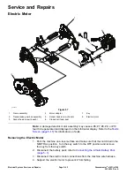

Electric Motor
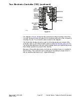
The electric motor is a 48 VDC, brushless, permanent magnet motor. The
electric motor has its own on-board controller (T5). If a problem exists with the
electric motor, a fault may have occurred that would be indicated by a fault code
on the InfoCenter Display. Before considering that electric motor service work
is necessary, check for any existing fault codes that indicate problems with the
electric motor; refer to
Machine Faults (page 3–5)
. If the electric motor is faulty,
there will likely be numerous fault codes that are listed by the InfoCenter display.
To operate, the electric motor requires 48V logic power (supplied by the logic
relay) and a connection to the 48V power bus (supplied by the main contactor
when energized).
The electric motor controller is not serviceable. Refer to
Appendix A (page A–1)
for circuit wiring information.
Note:
If the electric motor is replaced for any reason, the machine software must
be updated; contact an Authorized Toro Distributor for assistance.
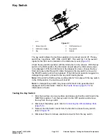
Testing the Electric Motor
1. Park the machine on a level surface and make sure that the clutch bail in the
NEUTRAL position. Turn the key switch to the OFF position and remove
the key from the key switch.
2. Disconnect the battery pack; refer to
Connecting the Lithium Battery Pack
(page 5–3)
.
3. Locate and disconnect the electric motor cable electrical connections at the
machine wire harness. Check the motor and the harness connector for
damage or corrosion and clean or repair as necessary.
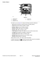
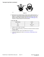
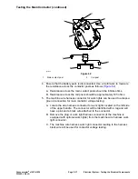
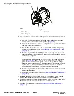
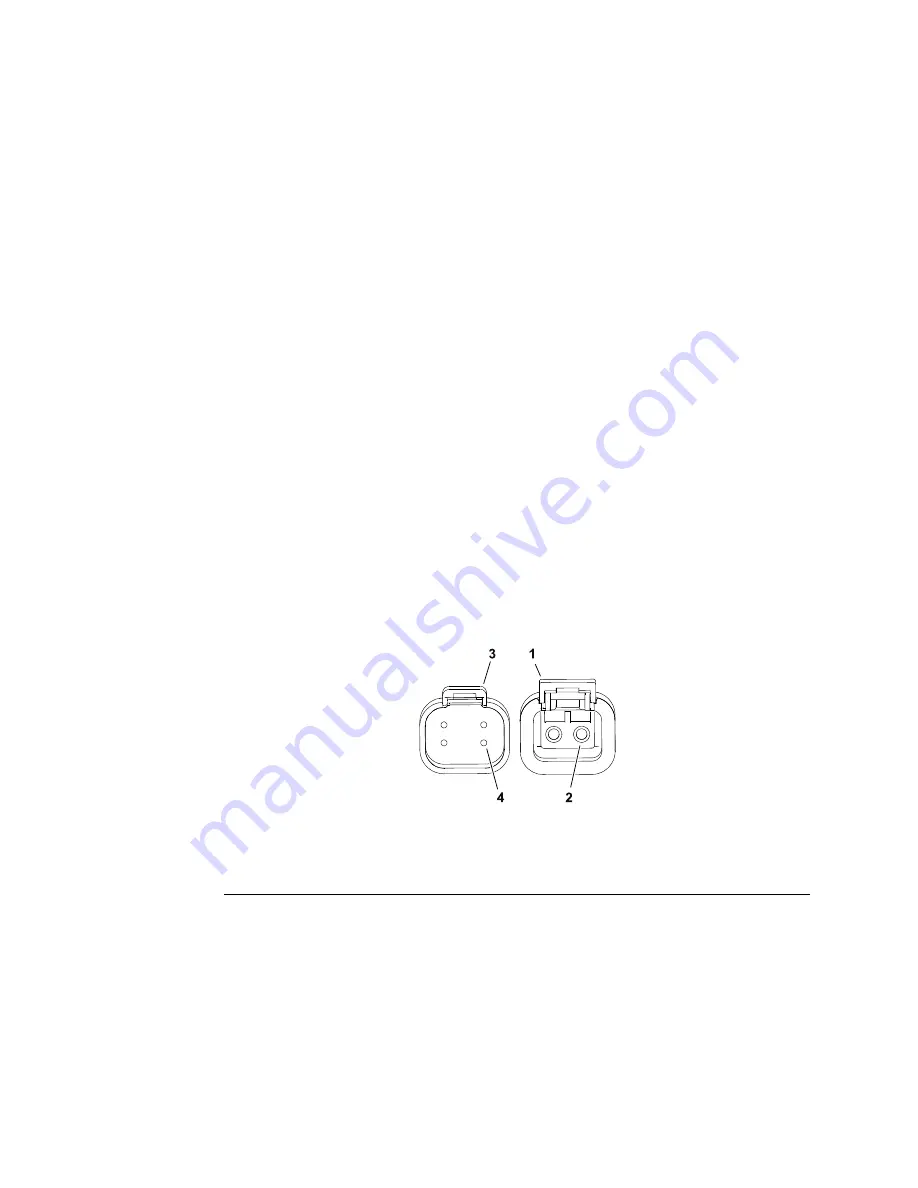
4. Use a multimeter (ohms setting) measure the resistance between the ground
terminal (black wire) and the pin two in four pin connector. Resistance should
be approximately 18.8 K-ohms.
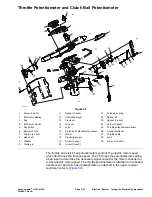
g289715
Figure 56
1.
Electric motor connector – 2 pin
3.
Electric motor connector – 4 pin
2.
Ground terminal
4.
Pin 2
5. If electric motor removal, installation, disassembly or assembly is required;
refer to
Electric Motor (page 5–42)
.
6. If the motor tests correctly and a problem still exits, check the rear wheel
traction motor circuit wiring; refer to
Appendix A (page A–1)
.
7. After testing is complete, secure the electric motor wire harness connectors.
8. Connect the battery pack; refer to
Connecting the Lithium Battery Pack
(page 5–3)
.
Electrical System: Testing the Electrical Components
Page 5–30
Greensmaster
®
e1021/e1026
20246SL Rev A
Содержание 04831
Страница 4: ...NOTES NOTES Page 4 Greensmaster e1021 e1026 20246SL Rev A ...
Страница 6: ...g340650 Figure 1 Model 04831 shown Preface Page 6 Greensmaster e1021 e1026 20246SL Rev A ...
Страница 14: ...Safety Safety and Instructional Decals Page 1 6 Greensmaster e1021 e1026 20246SL Rev A ...
Страница 46: ...Troubleshooting Battery Charger Error and Fault Codes Page 3 14 Greensmaster e1021 e1026 20246SL Rev A ...
Страница 136: ...Electrical System Service and Repairs Page 5 56 Greensmaster e1021 e1026 20246SL Rev A ...
Страница 162: ...Controls Wheels and Accessories Service and Repairs Page 6 26 Greensmaster e1021 e1026 20246SL Rev A ...
Страница 210: ...Universal Groomer Optional Service and Repairs Page 8 20 Greensmaster e1021 e1026 20246SL Rev A ...
Страница 213: ...Greensmaster e1021 e1026 Drawing 122 1647 Rev A Sheet 1 of 1 20246SL Rev A Page A 3 Electrical Schematic g361655 ...
Страница 214: ...Page A 4 20246SL Rev A Greensmaster e1021 e1026 Drawing 122 1734 Rev D Sheet 1 of 2 Wire Harness Drawing CV g361656 ...
Страница 215: ...Greensmaster e1021 e1026 Drawing 122 1734 Rev D Sheet 2 of 2 20246SL Rev A Page A 5 Wire Harness Drawing g361657 ...
Страница 216: ......


