1
Installing the Handle
Parts needed for this procedure:
1
Handle
Procedure
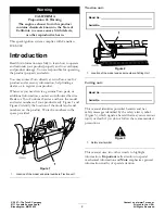
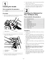
1. Remove the flange lock nut from the bolt and pivot
pin on each side of the mower (Figure 4).
Figure 4
1.
Flange lock nut
2.
Pivot pin
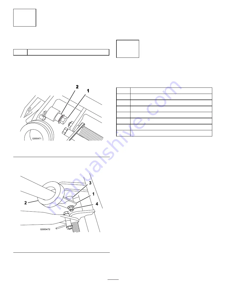
2. Insert the handle ends through the slots in the handle
support arms (Figure 5).
Figure 5
1.
Left handle end
3.
Pivot pin
2.
Support arm
4.
Locknut
3. Squeeze the handle ends inward and install them on
the step of the pivot pin (Figure 5).
4. Secure the handle to the bolt and pivot pin with the
flange lock nut (Figure 5).
5. Locate cable tie loosely securing throttle cable to
wire harness. Position cable tie approximately one
inch behind transmission and tighten cable tie.
2
Installing the Kickstand for
Flex 18 Mowers Only
Parts needed for this procedure:
1
Kickstand assembly
1
Spring
1
Small spacer
1
Large spacer
1
Large bolt (M8–1.25 x 100)
1
Small bolt (M8–1.25 x 030)
2
Locknut (M8 x 1.25)
2
Washer (M8)
Procedure
1. Position the kickstand between the tabs on the rear
of the frame.
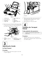
2. Install a washer (M8) onto the small bolt (M8–1.25
x 030). Install the right side of the kickstand to the
frame with the bolt and washer, the small spacer,
and locknut (M8–1.25) (Figure 6). Ensure the bolt
is installed from the inside of the frame as shown
in Figure 6.
3. Install a washer (M8) onto the large bolt (M8–1.25 x
100).
4. Install the spacer into the spring and install the large
bolt (M8–1.25 x 100) into the spacer.
Important:
When installing the spring, place
one end of the spring under the rear frame
(Figure 6).
5. Install the left side of the kickstand to the frame
with the bolt and washer, the large spacer and spring,
and locknut (M8–1.25) (Figure 6). Ensure the bolt
is installed from the inside of the frame as shown
in Figure 6.
11
Содержание 04030
Страница 39: ...Notes 39 ...


